
Controlled diffuse scattering for displays

a technology of diffuse scattering and display, applied in the field of electronic devices, can solve the problems of not necessarily optimal diffusers, deleterious effects on black state and color saturation,

Active Publication Date: 2013-12-19
DEAN KENNETH A +2
View PDF7 Cites 11 Cited by
  • Summary
  • Abstract
  • Description
  • Claims
  • Application Information

AI Technical Summary

Benefits of technology

The patent text discusses the problem of limited brightness and contrast in reflective displays, which are used in electronic devices like e-readers and tablets. These displays require more power, have lower battery life, and can cause eye strain. The text proposes a solution by incorporating electrofluidic devices that provide optical response for the purpose of altering surface reflectivity, transmission through surface, or creating 2D or 3D images for informational display. The patent text also discusses the issue of lateral color arrangements on reflective displays, which have not been widely commercially successful. The text concludes by stating that there is a need for monochrome and color displays with improved diffuse scattering properties for maximizing brightness and contrast. The patent text references several prior art solutions and proposes a new solution to address the problem of limited brightness and contrast in reflective displays.

Problems solved by technology

In the most preferred embodiments, the a textured metallic reflector is the channel electrode and lies adjacent to the ink, or a white film (e.g., titania-loaded photoresist, white polymer, or stamped white ink), may be positioned directly underneath an ink or polar fluid electrode. or In a circumstance where a white PET film is used as at least part of the reflective backing material, the white film may be about 1 mm behind the plane of the colorant to provide an effective diffuser, but not necessarily an optimal diffuser.
Another point is that white, diffuse reflectance can be obtained without the use of haze filters, which have deleterious effects on the black state and color saturation.

Method used


Image

  • Controlled diffuse scattering for displays
  • Controlled diffuse scattering for displays
  • Controlled diffuse scattering for displays

Examples


Embodiment Construction

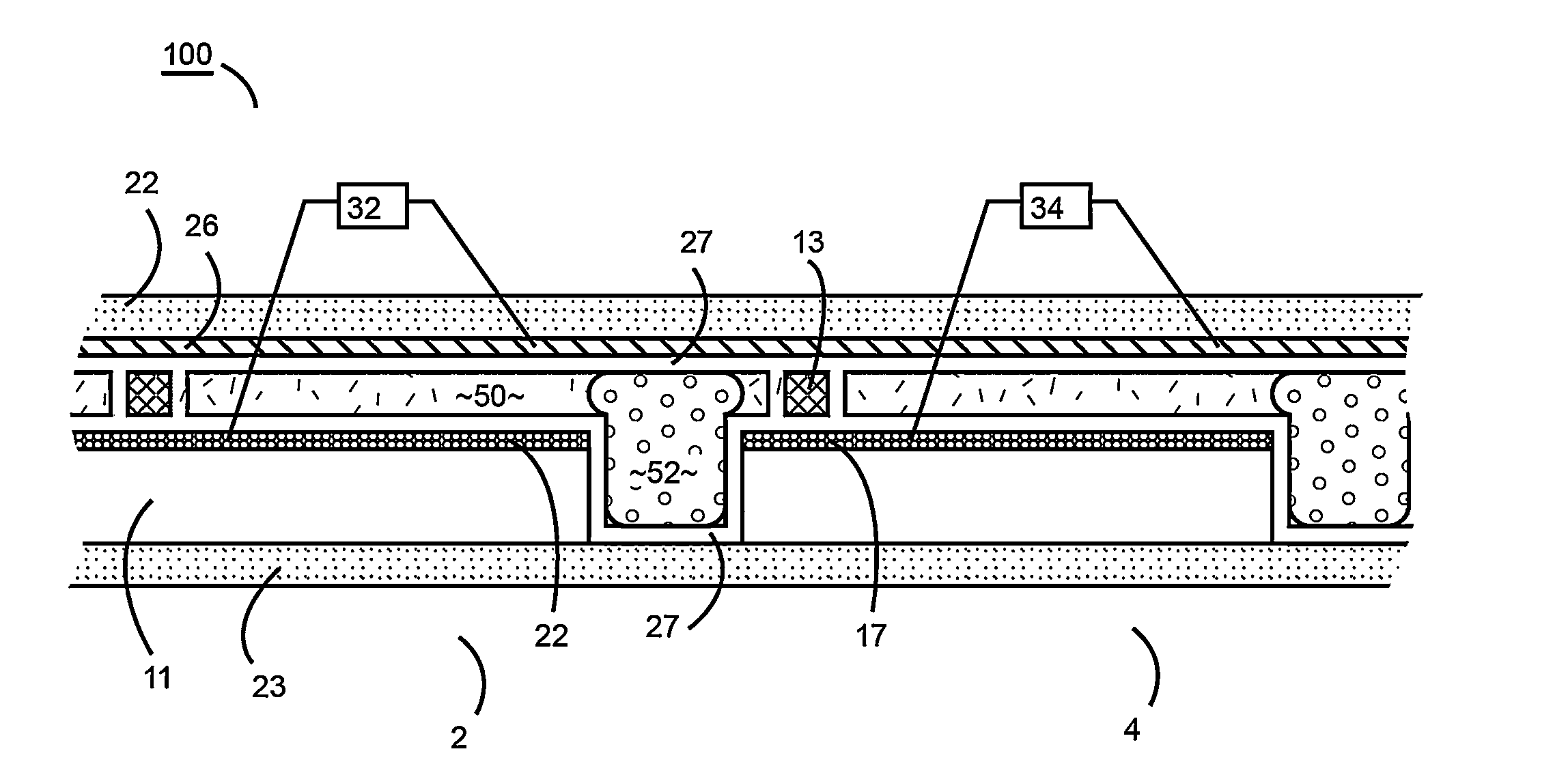
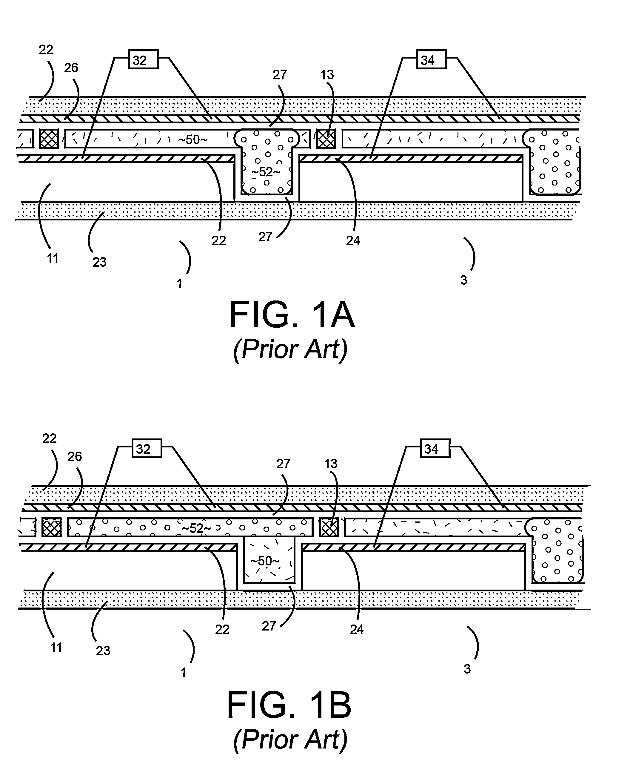
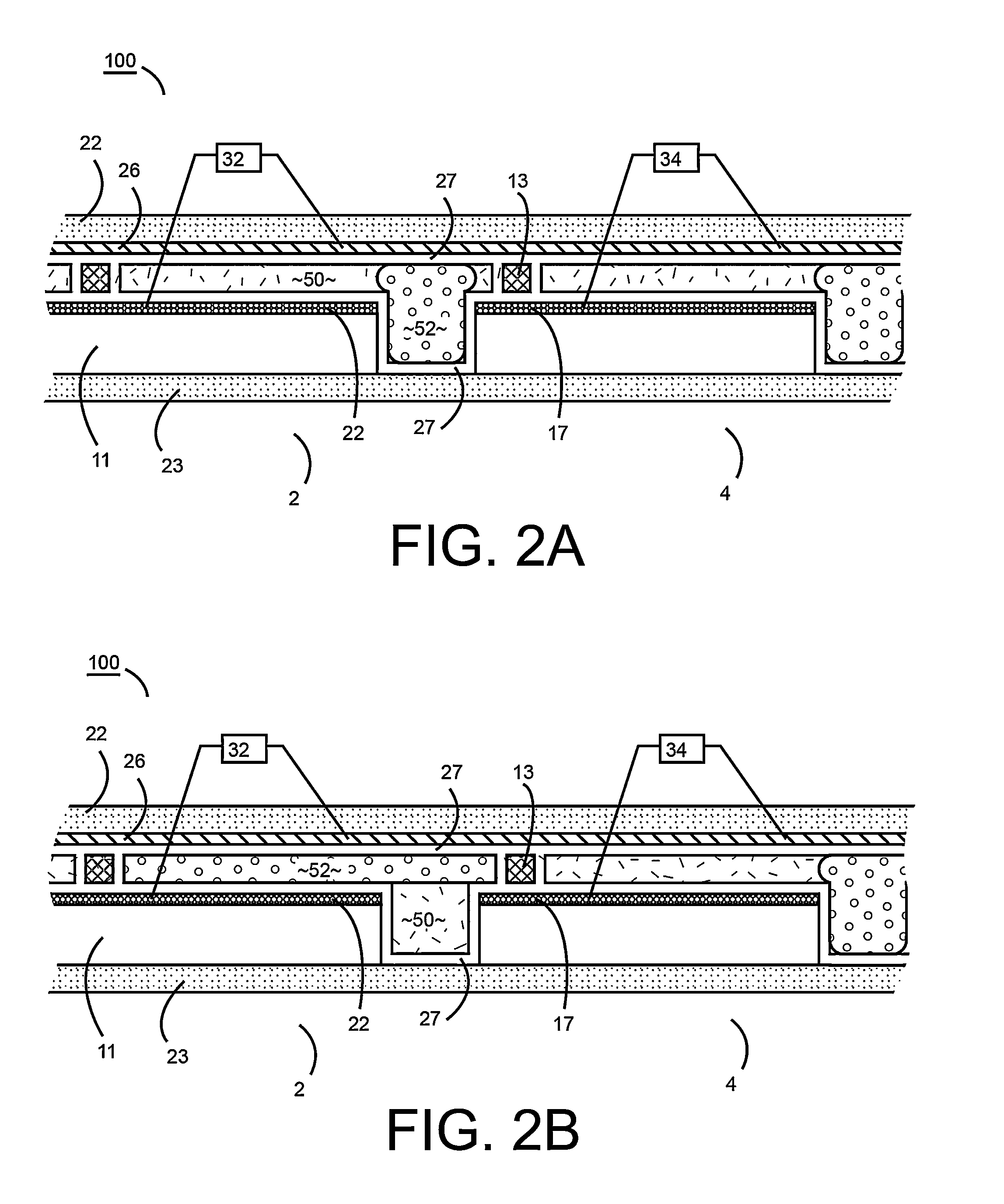
[0039]The exemplary embodiments of the present disclosure are described and illustrated below to encompass a device, a specifically-textured reflective surface in combination with a high efficiency electrofluidic light valve, to achieve brightness and color performance of printed ink-on-paper media. Of course, it will be apparent to those of ordinary skill in the art that the embodiments discussed below are exemplary in nature and may be reconfigured without departing from the scope and spirit of the present disclosure. However, for clarity and precision, the exemplary embodiments as discussed below may include optional steps, methods, and features that one of ordinary skill should recognize as not being a requisite to fall within the scope of the present disclosure.

[0040]Referencing FIGS. 1A and 1B, an electromechanical force on a conductive fluid on an electrical insulator underlies the physical mechanism for a first exemplary embodiment of the present disclosure. This electromech...


PUM


Abstract

A display device comprising a pixel, where the pixel includes: (a) a polar fluid that is at least one of colored and black, (b) a non-polar fluid that is at least one of transparent and translucent, (c) a first substrate, (d) a second substrate arranged relative to the first substrate to define a channel occupied by the polar fluid and the non-polar fluid, wherein at least one of the polar fluid and the non-polar fluid is visible through at least one of the first substrate and the second substrate, (e) a reflector having a plurality of features, comprising at least one of concavities and projections, that alter an angle of reflected light from a specular reflection to provide the appearance of at least one of a diffuse reflection and a non-metallic reflection, where the reflector includes a hydrophobic coating causing the polar fluid that is at least one of colored and black to be non-wetting to the hydrophobic coating in the presence of the non-polar fluid, the display device also including a plurality of electrodes configured to cause repositioning of the polar fluid in the channel to displace at least a first portion of the non-polar fluid and a voltage source, where repositioning of the polar fluid occurs as a unified volume to retard reduced light reflection from the reflector in a portion of the channel where the polar fluid has been repositioned.

Description

CROSS REFERENCE TO RELATED APPLICATIONS[0001]The present application claims the benefit of U.S. Provisional Patent Application Ser. No. 61 / 632,248, filed on Jan. 19, 2012 and titled, “CONTROLLED DIFFUSE SCATERING FOR DISPLAYS,” the disclosure of which is hereby incorporated by reference.RELATED ART[0002]1. Field of the Invention[0003]The present disclosure relates to electrofluidic devices that provide an optical response for the purpose of altering surface reflectivity, transmission through a surface, or creating 2D or 3D images for informational display.[0004]2. Brief Discussion of Related Art[0005]Consumers are used to reading printed media formed from ink printed on paper. The brightness, whiteness, and contrast of ink on paper provides a reading experience that meets a consumers needs both indoors and outdoors. Emissive displays such as LCDs that are using in computers, tablets, phones, and digital cameras are more difficult to read, causing eye strain, and are simply unreadabl...

Claims


Application Information

Patent Timeline
Patent Type & Authority Applications(United States)
IPC IPC(8): G02B26/00
CPCG02B26/005G02B26/004G02B26/0841G02F1/07
Inventor DEAN, KENNETH A.RUDOLPH, JOHNYANG, SHU
Owner DEAN KENNETH A
Learn More