ASE Swept Source with Self-Tracking Filter for OCT Medical Imaging

a technology of self-tracking filter and swept source, which is applied in the direction of instruments, semiconductor lasers, lighting and heating apparatus, etc., can solve the problems of multiple tunable filters, affecting the synchronization of filters, and affecting the spectral width of signals, so as to reduce the requirement for filter synchronization, narrow the signal spectral width, and reduce the effect of accuracy

Inactive Publication Date: 2013-12-05
EXCELITAS TECH
View PDF1 Cites 5 Cited by
  • Summary
  • Abstract
  • Description
  • Claims
  • Application Information

AI Technical Summary

Benefits of technology

The invention is a swept source that uses a tunable filter in a self-tracking configuration to address problems with filter synchronization and reduce ASE emissions. This configuration narrows the spectral width of the signal, which is needed for deeper imaging, and avoids the need for complex synchronization of the two filters. The technical effect is improved performance and efficiency of the swept source for optical imaging applications.

Problems solved by technology

As a result, this narrowband signal is relatively weak in power since most of the light generated by the seed ASE source is rejected and therefore not used.
This arises because when the relatively weak signal from the primary filter is amplified, there is a large contribution of additive broadband optical noise outside the passband of the primary tunable filter, with the added noise power that is comparable to the signal power itself.
The use of multiple tunable filters creates its own problems, however.
Their passbands must be precisely aligned in wavelength as both filters are being tuned, otherwise the power level of the output signal light will be severely degraded.
This further complicates the filter alignment task, requiring very precise high-speed dynamic filter tuning synchronization.
This reduces the accuracy with which the tracking filter must track the operation of the primary filter.
There is a downside, however, to this narrow-wide filter configuration.
Finally, the filters can drift differently over time, leading to a need to calibrate the filter tuning system or to a complex filter tuning control loop.

Method used


Image

  • ASE Swept Source with Self-Tracking Filter for OCT Medical Imaging
  • ASE Swept Source with Self-Tracking Filter for OCT Medical Imaging
  • ASE Swept Source with Self-Tracking Filter for OCT Medical Imaging

Examples


Embodiment Construction

[0051]In the following description similar components in the different embodiments are given the same or similar reference numerals to indicate similar construction and functionality.

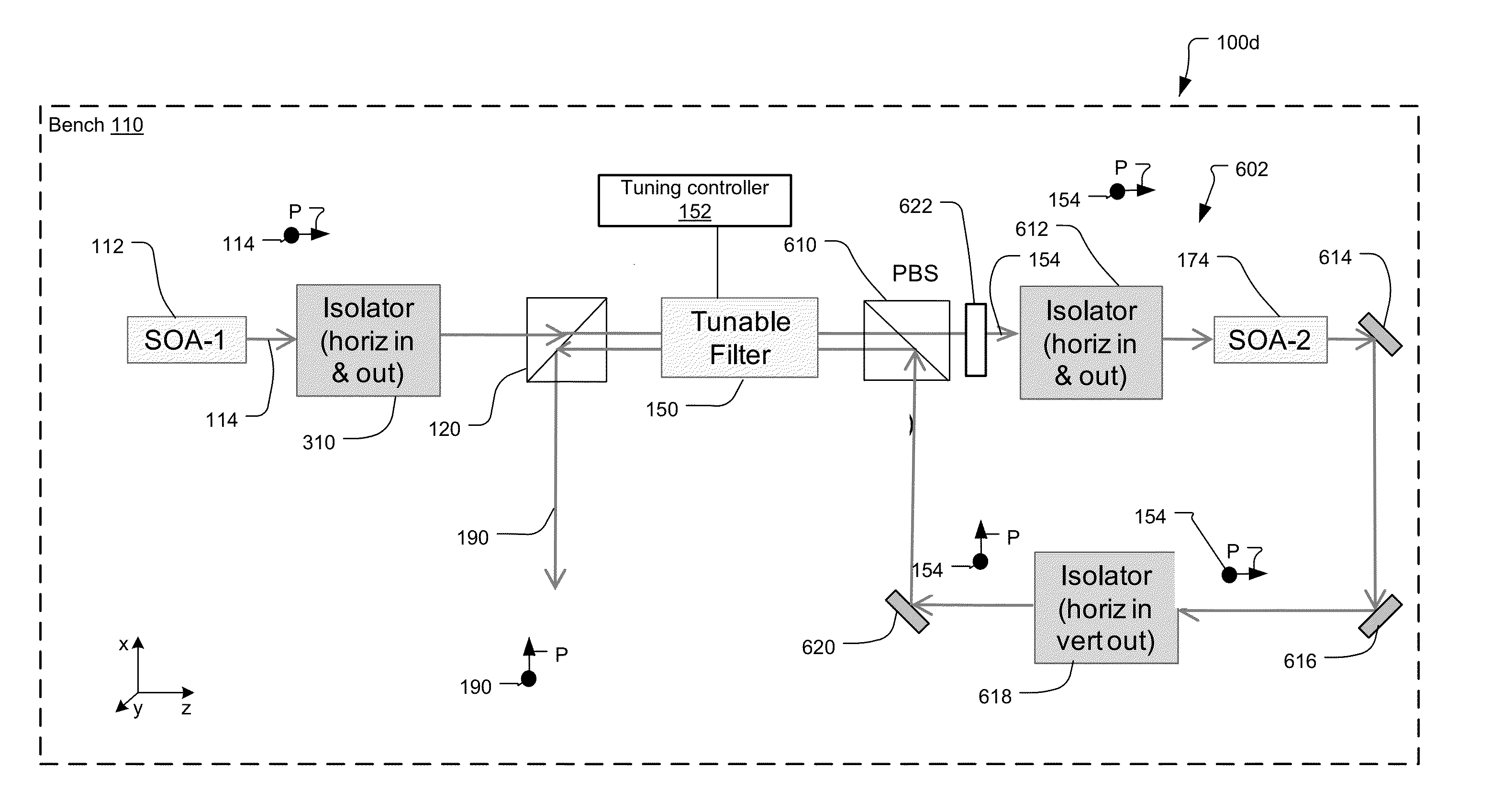
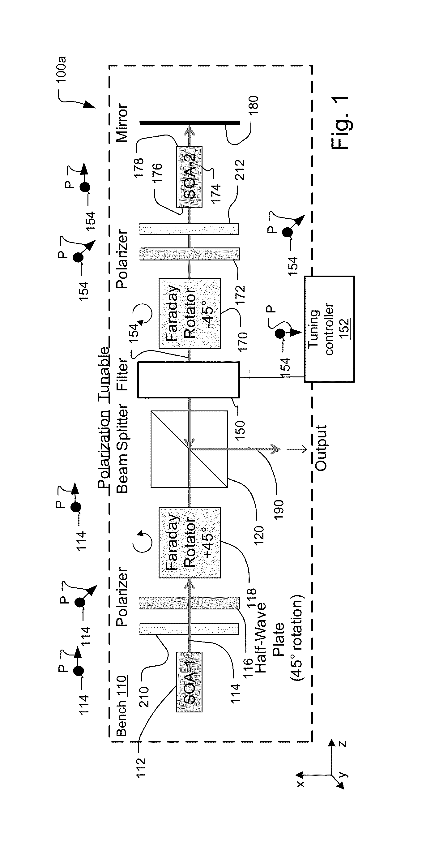
[0052]FIG. 1 shows a first embodiment swept optical source 100a with contra-directional self-tracking filter using polarization diversity and a reflective, double-pass amplification stage, which has been constructed according to the principles of the present invention.

[0053]Preferably, the source 100a is entirely implemented on a single bench 110 with free space optics coupling the optical beams between the optical elements. In the coordinate system of the figure, the bench extends in the x-z plane and the y-axis extends vertically from the plane of the bench.

[0054]In other examples, many or most of the optical elements are implemented in common on a single optical bench. In yet other examples, two or more separate optical benches are used to implement the swept source, placing some optical components o...


PUM


Abstract

An integrated swept wavelength tunable optical source uses a narrowband filtered broadband signal with an optical amplifier and self-tracking filter. This source comprises a micro optical bench, a source for generating broadband light, a tunable Fabry Perot filter, installed on the bench, for spectrally filtering the broadband light from the broadband source to generate a narrowband tunable signal, an amplifier, installed on the bench, for amplifying the tunable signal. The self-tracking arrangement is used where a single tunable filter both generates the narrowband signal and spectrally filters the amplified signal. In some examples, two-stage amplification is provided. The use of a single bench implementation yields a low cost high performance system. For example, polarization control between components is no longer necessary.

Description

RELATED APPLICATIONS[0001]This application is a Divisional of U.S. application Ser. No. 12 / 776,373, filed on May 8, 2010, now U.S. Patent Publication No.: US 2011 / 0051143 A1, which is a Continuation-in-Part (CIP) of U.S. application Ser. No. 12 / 553,295, filed on Sep. 3, 2009, now U.S. Patent Publication No.: 2011 / 0051148 A1. Both applications are incorporated herein by reference in their entirety.[0002]This application is related to U.S. application Ser. No. 13 / 847,616 filed on Mar. 20, 2013.BACKGROUND OF THE INVENTION[0003]Optical coherence analysis relies on the use of the interference phenomena between a reference wave and an experimental wave or between two parts of an experimental wave to measure distances and thicknesses, and calculate indices of refraction of a sample. Optical Coherence Tomography (OCT) is one example technology that is used to perform usually high-resolution cross sectional imaging. It is often applied to imaging biological tissue structures, for example, on...

Claims


Application Information

Patent Timeline
Patent Type & Authority Applications(United States)
IPC IPC(8): F21V9/00G01B9/02
CPCF21V9/00G01B9/02091F21V9/20G01B9/02004H01S5/005H01S5/0064H01S5/0078H01S5/02216H01S5/5018H01S5/5036H01S5/5063H01S2301/02H01S5/02251H01S5/02325
Inventor FLANDERS, DALE C.ATIA, WALID A.KUZNETSOV, MARK E.
Owner EXCELITAS TECH
Why Eureka
Try Eureka