Antenna device for portable terminal

a portable terminal and antenna device technology, applied in the field of portable terminals, can solve the problems of degrading the efficiency of the circuit board b>11/b> relative to the area affecting the miniaturization and slimmerization of the portable terminal, and reducing the efficiency of the circuit board b>11/b>, so as to achieve the effect of efficient use of the internal space and miniaturization and slimmer

Active Publication Date: 2013-12-05
SAMSUNG ELECTRONICS CO LTD
View PDF11 Cites 5 Cited by
  • Summary
  • Abstract
  • Description
  • Claims
  • Application Information

AI Technical Summary

Benefits of technology

This patent describes an antenna system that can be made smaller and slimmer for use in mobile devices. The system works efficiently and effectively within the limited space of the device.

Problems solved by technology

However, it is substantially impossible to mount another part in the fill cut region 15 on the circuit board 11, such that the use efficiency of the circuit board 11 relative to the area of the circuit board 11 is degraded.
Eventually, the IFA structure, in spite of its super-high speed and broadband performance and usefulness in mounting on the portable terminal, is still an obstacle to miniaturization and slimmerization of the portable terminal.

Method used


Image

  • Antenna device for portable terminal
  • Antenna device for portable terminal
  • Antenna device for portable terminal

Examples


Embodiment Construction

[0030]FIGS. 2 through 12, discussed below, and the various embodiments used to describe the principles of the present disclosure in this patent document are by way of illustration only and should not be construed in any way to limit the scope of the disclosure. Those skilled in the art will understand that the principles of the present disclosure may be implemented in any suitably arranged wireless communications device. Hereinafter, an exemplary embodiment of the present invention will be described in detail with reference to the accompanying drawings. Herein, a detailed description of well-known structures will not be provided if it unnecessarily obscures the subject matter of the present invention.

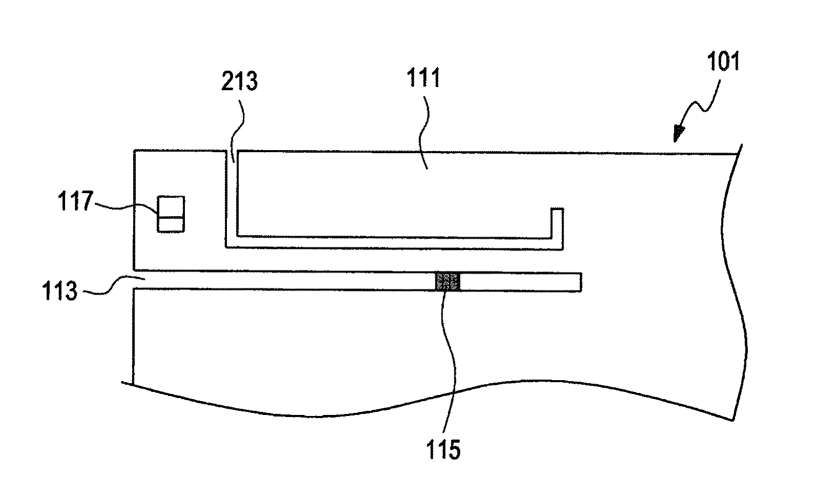
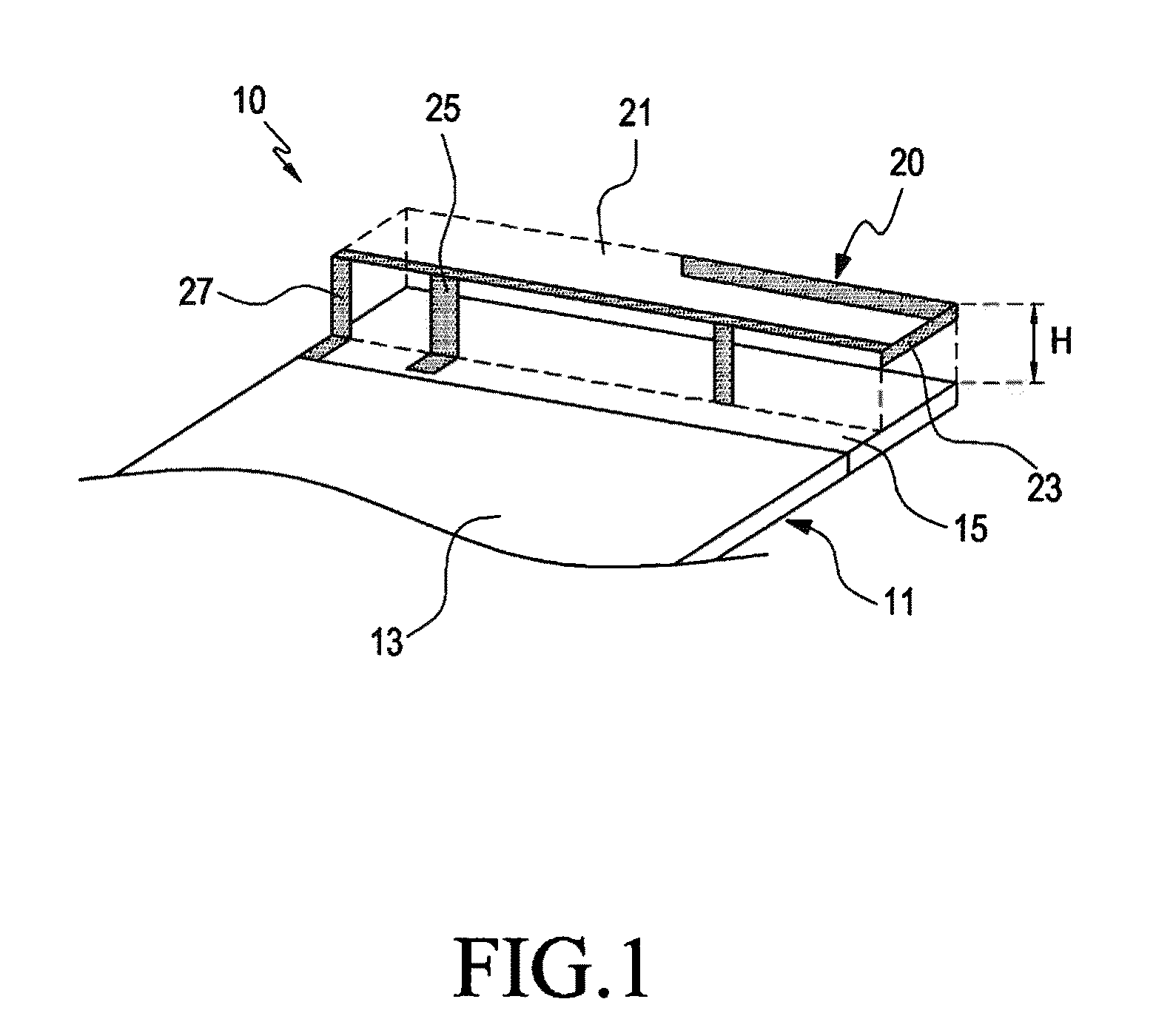
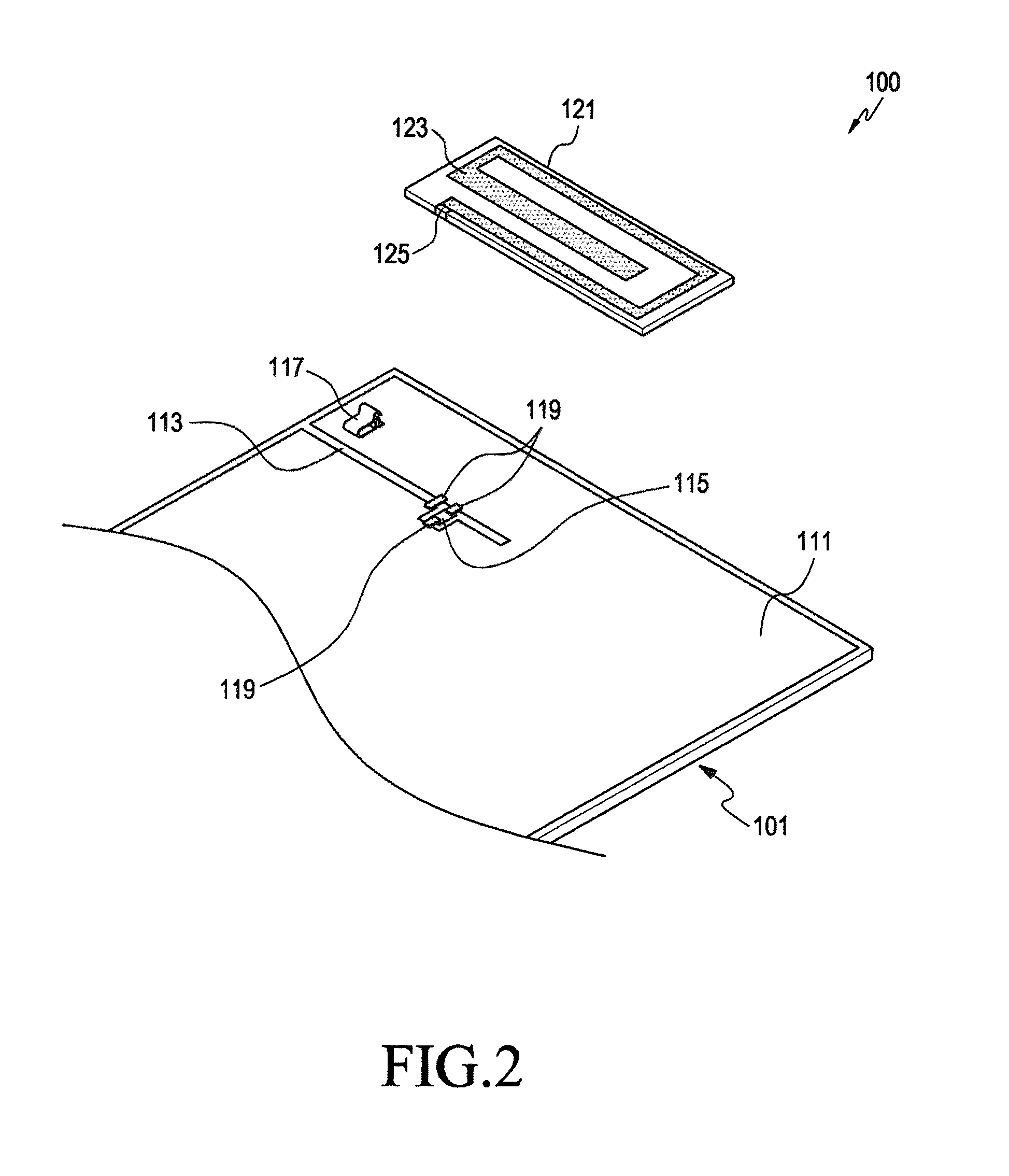
[0031]As shown in FIGS. 2 through 7, an antenna device 100 for a portable terminal according to an embodiment of the present disclosure includes a circuit board 101 on which a conductive layer 111 is formed and an auxiliary board 121 on which a radiation pattern 123 is formed. The radia...


PUM


Abstract

A portable terminal includes an antenna device having a circuit board on a surface of which a conductive layer is formed, a slit that removes a portion of the conductive layer and extends in a direction, an auxiliary board positioned on the slit to face a surface of the circuit board, and a radiation pattern formed on the auxiliary board, in which the radiation pattern is disposed to partially enclose the slit. Even when the radiation pattern is disposed on the conductive layer, induced current generated around the slit can be controlled in the same direction as signal power, thereby preventing radiation performance from being degraded by an inverse current phenomenon in spite of disposition of the radiation pattern on the conductive layer.

Description

CROSS-REFERENCE TO RELATED APPLICATION(S) AND CLAIM OF PRIORITY[0001]The present application is related to and claims the benefit under 35 U.S.C. §119(a) of a Korean Patent Application filed in the Korean Intellectual Property Office on May 29, 2012 and assigned Serial No. 10-2012-0056451, the entire disclosure of which is hereby incorporated by reference.TECHNICAL FIELD OF THE INVENTION[0002]The present application generally relates to a portable terminal, and more particularly, to an antenna device for a portable terminal.BACKGROUND OF THE INVENTION[0003]Generally, a portable terminal refers to an apparatus carried by a user to execute a communication function with another user, such as voice communication, short text message transmission, or the like, a data communication function such as Internet, mobile banking, multimedia file transmission, or the like, and an entertainment function such as games, music, moving image reproduction, or the like. The portable terminal is generall...

Claims


Application Information

Patent Timeline
Patent Type & Authority Applications(United States)
IPC IPC(8): H01Q1/38H01Q1/50H01Q13/10
CPCH01Q1/243H01Q1/48H01Q1/528H01Q9/42H01Q13/10H01Q5/364H01Q5/392H01Q1/24H01Q9/04
Inventor CHO, BUM-JINKIM, GYU-SUBBYUN, JOON-HO
Owner SAMSUNG ELECTRONICS CO LTD
Why Eureka
Try Eureka