Eureka AIR delivers breakthrough ideas for toughest innovation challenges, trusted by R&D personnel around the world.

Light reflection plate

Inactive Publication Date: 2013-11-28
SEKISUI PLASTICS CO LTD
View PDF2 Cites 13 Cited by
  • Summary
  • Abstract
  • Description
  • Claims
  • Application Information

AI Technical Summary

Benefits of technology

The present invention relates to a light reflection plate with high light reflection performance and light diffusibility. The light reflection plate includes a particular amount of small primary particles that provide high light reflection performance and a particular amount of agglomerated particles that have higher light diffusibility than the primary particles. The light reflection plate also includes a coated titanium oxide layer that absorbs ultraviolet light and prevents photocatalysis, resulting in high light reflection performance and light diffusibility for a long time without coloration. The technical effects of the invention include improved light reflection performance and light diffusibility, reduced thickness of the light diffusion layer, and improved production efficiency.

Problems solved by technology

However, the above reflection film poses a problem in that the light reflection performance and the uniformity of light reflection in terms of light diffusion are not sufficiently achieved.
On the other hand, titanium oxide poses the following problem.
The titanium oxide used in the reflection film disclosed in PTL 1 is a titanium oxide that poses the above problem.
Therefore, the reflection film poses a problem in that the light reflectance decreases with usage of the reflection film.

Method used


Image

  • Light reflection plate
  • Light reflection plate
  • Light reflection plate

Examples


example 1

[0146]A coated titanium oxide A (trade name “CR-93” manufactured by ISHIHARA SANGYO KAISHA, LTD., average particle size: 0.28 μm) was prepared. In the coated titanium oxide A, a surface of rutile-type titanium oxide was coated with a coating layer containing aluminum oxide and silicon oxide. The amount of the aluminum oxide in the coated titanium oxide A was quantitatively determined by X-ray fluorescence analysis. The amount was 3.1% by weight in terms of Al2O3 relative to the total weight of titanium dioxide. The amount of the silicon oxide in the coated titanium oxide A was also quantitatively determined by X-ray fluorescence analysis. The amount was 4.2% by weight in terms of SiO2 relative to the total weight of titanium dioxide.

[0147]The coated titanium oxide A was dried by performing heating at 100° C. for 5 hours to decrease the amount of water of hydration contained in the coated titanium oxide. Then, 53.8 parts by weight of the coated titanium oxide A in which the amount of...

example 2

[0149]A light reflection plate was produced in the same manner as in Example 1, except that a coated titanium oxide B (trade name “CR-90” manufactured by ISHIHARA SANGYO KAISHA, LTD., average particle size: 0.25 μm) was used instead of the coated titanium oxide A.

[0150]In the coated titanium oxide B, a surface of rutile-type titanium oxide was coated with a coating layer containing aluminum oxide and silicon oxide. The amount of the aluminum oxide in the coated titanium oxide B was quantitatively determined by X-ray fluorescence analysis. The amount was 2.7% by weight in terms of Al2O3 relative to the total weight of titanium dioxide. The amount of the silicon oxide in the coated titanium oxide B was also quantitatively determined by X-ray fluorescence analysis. The amount was 3.6% by weight in terms of SiO2 relative to the total weight of titanium dioxide.

example 3

[0151]A light reflection plate was produced in the same manner as in Example 1, except that a coated titanium oxide C (trade name “CR-80” manufactured by ISHIHARA SANGYO KAISHA, LTD., average particle size: 0.25 μm) was used instead of the coated titanium oxide A.

[0152]In the coated titanium oxide C, a surface of rutile-type titanium oxide was coated with a coating layer containing aluminum oxide and silicon oxide. The amount of the aluminum oxide in the coated titanium oxide C was quantitatively determined by X-ray fluorescence analysis. The amount was 3.3% by weight in terms of Al2O3 relative to the total weight of titanium dioxide. The amount of the silicon oxide in the coated titanium oxide C was also quantitatively determined by X-ray fluorescence analysis. The amount was 1.8% by weight in terms of SiO2 relative to the total weight of titanium dioxide.


PUM


Abstract

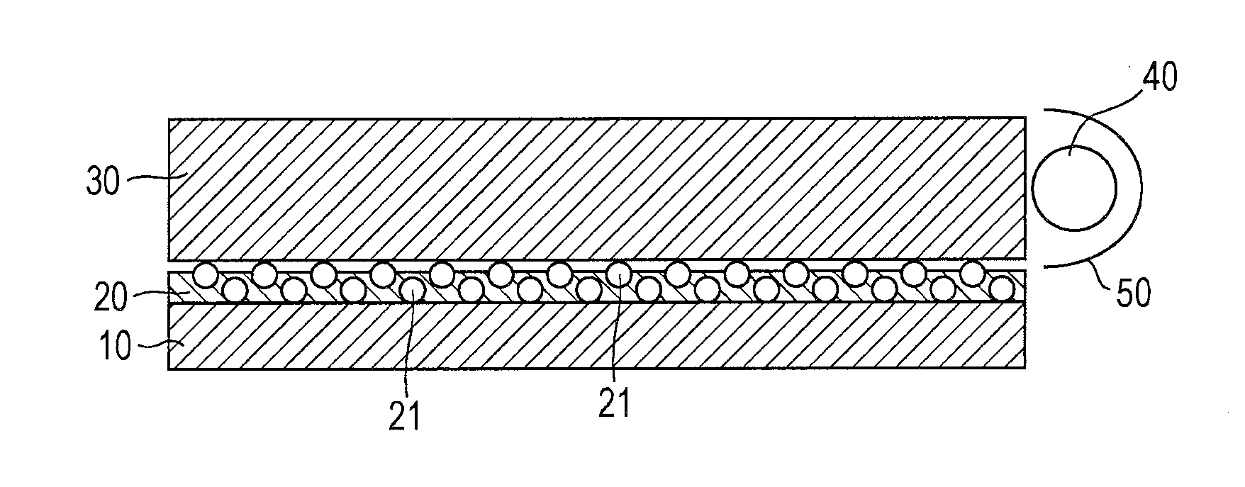
There is provided a light reflection plate that can uniformly exhibit high light diffusibility. The light reflection plate includes 100 parts by weight of a polyolefin-based resin and 20 to 120 parts by weight of a coated titanium oxide that is obtained by coating a surface of titanium oxide with a coating layer containing aluminum oxide and silicon oxide. The coated titanium oxide is constituted by primary particles having a particle size of 0.10 to 0.39 μm and agglomerated particles which are formed by agglomeration of the primary particles and have a particle size of 0.4 μm or more. The number of the agglomerated particles in a cross section of the light reflection plate in a thickness direction is 0.1 to 4.5 / 900 μm2 and the number of the primary particles, which are not agglomerated, in the cross section of the light reflection plate in the thickness direction is 1.5 to 11.0 / 900 μm2.

Description

TECHNICAL FIELD[0001]The present invention relates to a light reflection plate having high light reflection performance and light diffusibility.BACKGROUND ART[0002]In recent years, liquid crystal display apparatuses have been used in various applications as display apparatuses. In such liquid crystal display apparatuses, a backlight unit is disposed on a back surface of a liquid crystal cell. The backlight unit includes a light source such as a cold-cathode tube or an LED, a lamp reflector, a light-guiding plate, and a light reflection plate disposed on the back surface side of the light-guiding plate. The light reflection plate reflects, toward the liquid crystal cell, light leaked from the back surface of the light-guiding plate.[0003]The light reflection plate is, for example, a metal thin plate composed of aluminum or stainless steel, a film formed by depositing silver on a polyethylene terephthalate film, a metal foil prepared by laminating an aluminum foil, or a porous resin s...

Claims


Application Information

Patent Timeline
IPC IPC(8): G02B5/02
CPCG02B5/0226F21V7/0083G02B5/0866G02F1/133603G02F1/133605
Inventor HITOMI, KAZUTOSHISUZUKI, KENGO
Owner SEKISUI PLASTICS CO LTD
Why Eureka
Eureka Blog
Learn More