
Resin molded body and method of manufacturing same

Inactive Publication Date: 2013-11-21
SUZUKI MOTOR CO LTD
View PDF7 Cites 7 Cited by
  • Summary
  • Abstract
  • Description
  • Claims
  • Application Information

AI Technical Summary

Benefits of technology

The present invention is about a method for making a resin molded body with metallic texture and glittering appearance, which is currently achievable only through coating and plating processes. The method involves controlling the orientation of ferromagnetic glittering agent mixed in the resin through a required rotating magnetic field, resulting in a two-dimensional adjustment and concentration distribution of the agent. The resulting molded body has no defects or failures in external appearance and exhibits excellent metallic texture and glittering appearance. Additionally, the method can prevent weld lines, sink marks, and flow marks, which are common with resins. It is also free from peel-off and rust problems and reduces emissions of environmentally hazardous substances.

Problems solved by technology

Hence, if the addition rate of the glittering agent is as small as 0.1 to several percent, it is insufficient to impart metallic texture and glittering appearance to the resin molded body.
That is, the imparted metallic texture and glittering appearance are limited.
Unfortunately, if the addition rate thereof is increased, physical properties and functions as the resin material are impaired and economic efficiency is hence impaired due to the increase in costs.
If the weld line and the like occur in the resin molded body, a defect or trouble in the external appearance unique to the resin molded body easily shows up.
Unfortunately, in this case, physical properties and functions as the resin material are impaired, and economic efficiency is impaired due to the increase in costs.
However, even if only a small percent of the glittering agent is added, it is not possible to impart sufficient metallic texture and glittering appearance (for example, 3 or more in terms of a flip-flop value), so that the resin molded body cannot provide high-quality texture with metallic texture and glittering appearance.
Furthermore, in these days, any techniques for three-axis orientation control and orientation distribution control are not known.

Method used


Image

  • Resin molded body and method of manufacturing same
  • Resin molded body and method of manufacturing same
  • Resin molded body and method of manufacturing same

Examples


example 1

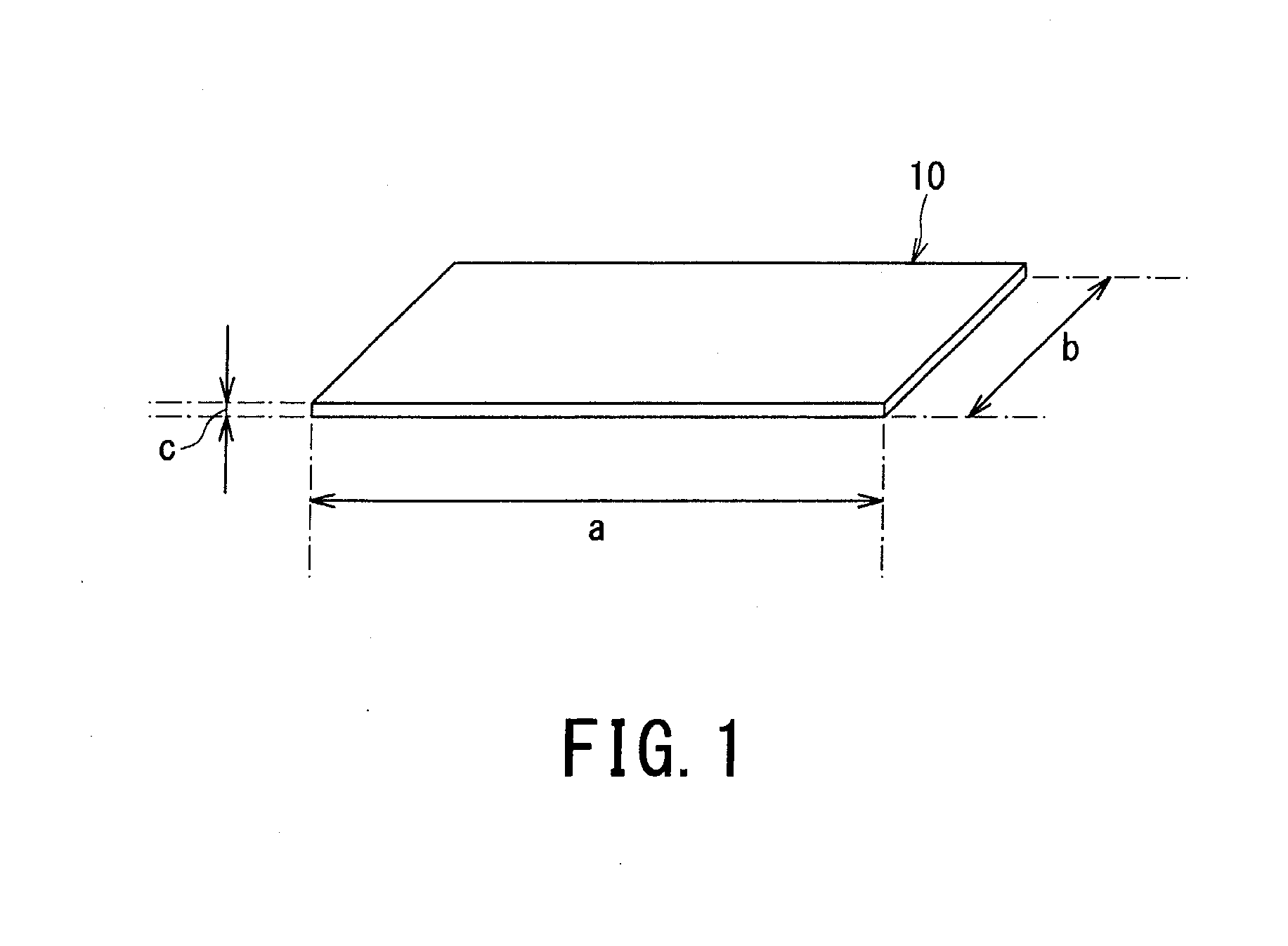
[0139]A room-temperature curing-type liquid silicone rubber having a viscosity of 100 Pa·s was prepared for the resin material as the sample 26. Scale-like PC permalloy flakes having an average particle diameter of 24 μm and an aspect ratio of 40 were prepared for the ferromagnetic glittering agent 10. Then, the prepared ferromagnetic glittering agent 10 was added and uniformly dispersed into the prepared sample 26 to thereby obtain a slurry. The addition rate of the ferromagnetic glittering agent 10 was as low as 10 wt % or less, for example, 2 wt %. The slurry thus obtained was poured into the non-magnetic glass container 25 (mold cavity) having a diameter of 20 mm and a thickness of 2 mm, and the container 25 was set on the rotating table 20 of the rotating magnetic field apparatus 15 illustrated in FIGS. 8A and 8B. In this state, an experiment was carried out.

[0140]Then, in the rotating magnetic field apparatus 15 illustrated in FIGS. 8A and 8B, a rotating magnetic field was app...

example 2

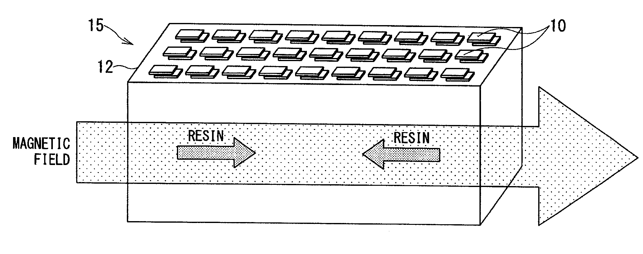
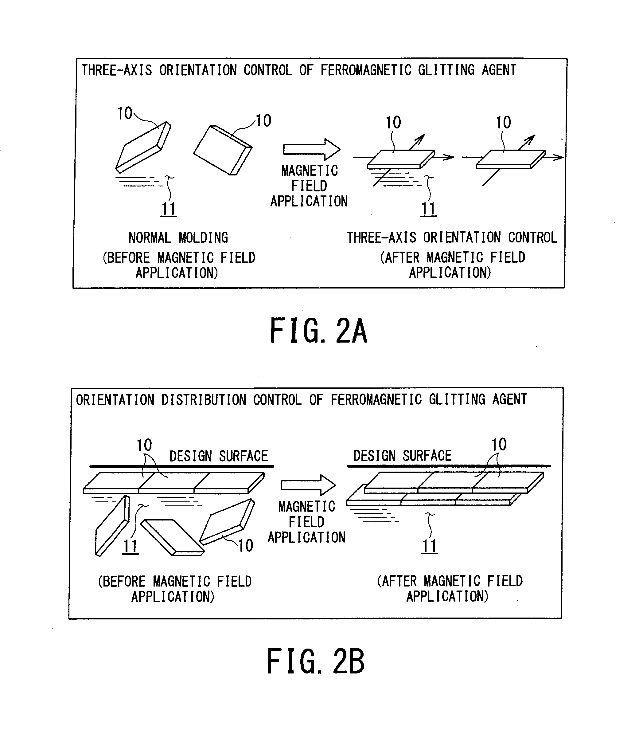
[0152]With regard to the three-axis orientation control on the ferromagnetic glittering agent, an experiment was carried out using the rotating magnetic field apparatus 16 illustrated in FIGS. 9A and 9B, in order to prove that the ab surfaces of all the particles of the ferromagnetic glittering agent 10 added to the resin material as the sample 26 faced the upper surface of the sample 26 (three-axis orientation control state). In the rotating magnetic field apparatus 16, the sample 26 was set in the area between the magnetic poles 17 and 18, the area having a uniform magnetic field without a magnetic field gradient. The experiment was carried out using the rotating magnetic field apparatus 16 under the condition that only the three-axis orientation control was performed on the permalloy flakes as the ferromagnetic glittering agent 10 added to the molten resin 11.

[0153]The scale-like PC permalloy flakes (ferromagnetic glittering agent 10) having an average particle diameter of 24 μm ...

example 3

[0155]With regard to the orientation distribution control on the ferromagnetic glittering agent, a corroborative experiment concerning shift movement was carried out using the PC permalloy flakes as the ferromagnetic glittering agent 10 of Example 1, in order to prove that the orientation (alignment) distribution of the ferromagnetic glittering agent 10 is controlled inside of the molten resin 11 of the sample 26.

[0156]In Example 3, the scale-like PC permalloy flakes (ferromagnetic glittering agent 10) having an average particle diameter of 24 μm and an aspect ratio of 40 were added and uniformly dispersed into a room-temperature curing liquid silicone rubber (resin material) having a viscosity of 100 Pa·s, thus obtaining a slurry.

[0157]The addition rate of the ferromagnetic glittering agent 10 was low, for example, 2 wt %. Further, an additive-free room-temperature curing liquid silicone rubber was set on the slurry thus obtained. Under this condition, the same experiment as that i...


PUM

PropertyMeasurementUnit
Particle sizeaaaaaaaaaa
Angular velocityaaaaaaaaaa

Abstract

A resin molded body includes a polymeric material, such as one of a thermoplastic resin, a thermosetting resin, elastomer, and rubber, to which a required amount of ferromagnetic glittering agent having shape anisotropy is added. At a time when the polymeric material is in a molten resin state inside of a mold cavity, the polymeric material is subjected to the three-axis orientation control and orientation distribution control performed by applying a rotating magnetic field to the molten resin at a required position, adjusting an orientation of the ferromagnetic glittering agent mixed in the molten resin, and shifting the ferromagnetic glittering agent mixed in the molten resin in a required direction, and the ferromagnetic glittering agent mixed in the molten resin is then shifted to a design surface side to be thereby concentratedly distributed for orientation.

Description

BACKGROUND OF THE INVENTION[0001]1. Field of the Invention[0002]The present invention relates to a resin material coloring technique using a ferromagnetic glittering agent or material added to a molten resin, and more particularly, to a resin molded body and a method of manufacturing the same. The resin molded body is formed by applying a desired rotating magnetic field to a shape-anisotropic ferromagnetic glittering agent added to the viscous body of a molten resin. The resin molded body can exhibit metallic texture and glittering appearance leading to high-quality texture, and can suppress a defect in external appearance.[0003]2. Related Art[0004]In recent years, colored resin materials are increasingly used for external appearance as resin molded bodies, for the purpose of a reduction in volatile organic compounds in terms of environmental measures and reduction in costs of resin components. The colored resin materials are not subjected to surface treatment such as coating and ar...

Claims


Application Information

Patent Timeline
IPC IPC(8): B44D5/10
CPCB44D5/10B29C45/0013B29C45/0025B29C2045/0015C08J3/201Y10T428/268Y10T428/249921
Inventor FUKAMI, YUNOSUKEKIMURA, TSUNEHISAKIMURA, FUMIKO
Owner SUZUKI MOTOR CO LTD
Learn More