Semiconductor laser
a semiconductor laser and laser technology, applied in the field of semiconductor lasers, can solve problems such as unstable oscillation mode, and achieve the effect of increasing the optical intensity around the center of the resonator acting in the semiconductor laser
- Summary
- Abstract
- Description
- Claims
- Application Information
AI Technical Summary
Benefits of technology
Problems solved by technology
Method used
Image
Examples
second embodiment
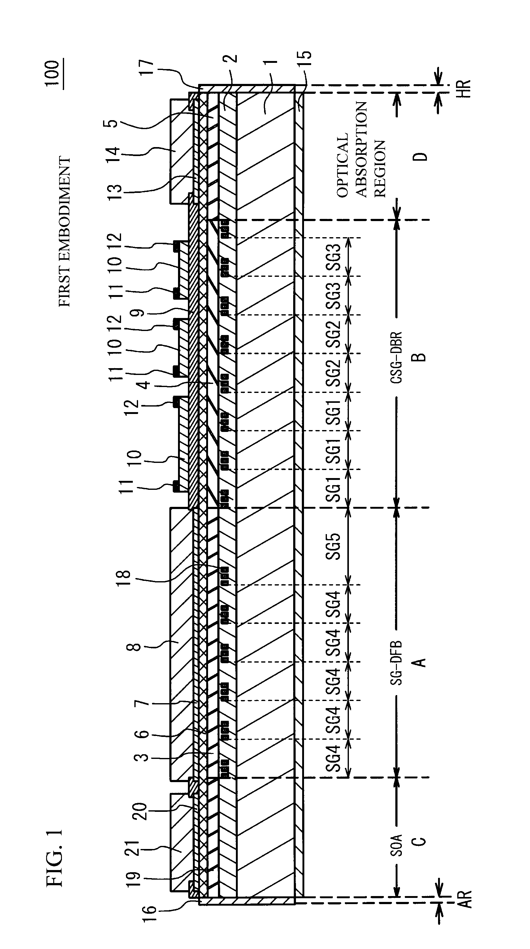
[0054]FIG. 5A illustrates a schematic cross sectional view of a semiconductor laser 100a in accordance with a second embodiment. The semiconductor laser 100a is different from the semiconductor laser 100 in a point that the optical length of the long-segment SG5 is larger than that of the short-segment SG4 by twice plus-minus 25% of the short-segment SG4. For example, the optical length of the short-segment SG4 is 160 μm. The optical length of the long-segment SG5 is 480 μm. The number of the short-segment SG4 is set to be four, because the long-segment SG5 gets longer. The length of the diffraction grating region of the short-segment SG4 and the long-segment SG5 is approximately 4 μm.
[0055]FIG. 5B illustrates an optical intensity distribution of a resonator in the semiconductor laser 100a. In FIG. 5B, a horizontal axis indicates a position of the resonator. A vertical axis indicates the optical intensity. In FIG. 5B, “Ps” indicates a propagation light toward the front side. “Pr” in...
third embodiment
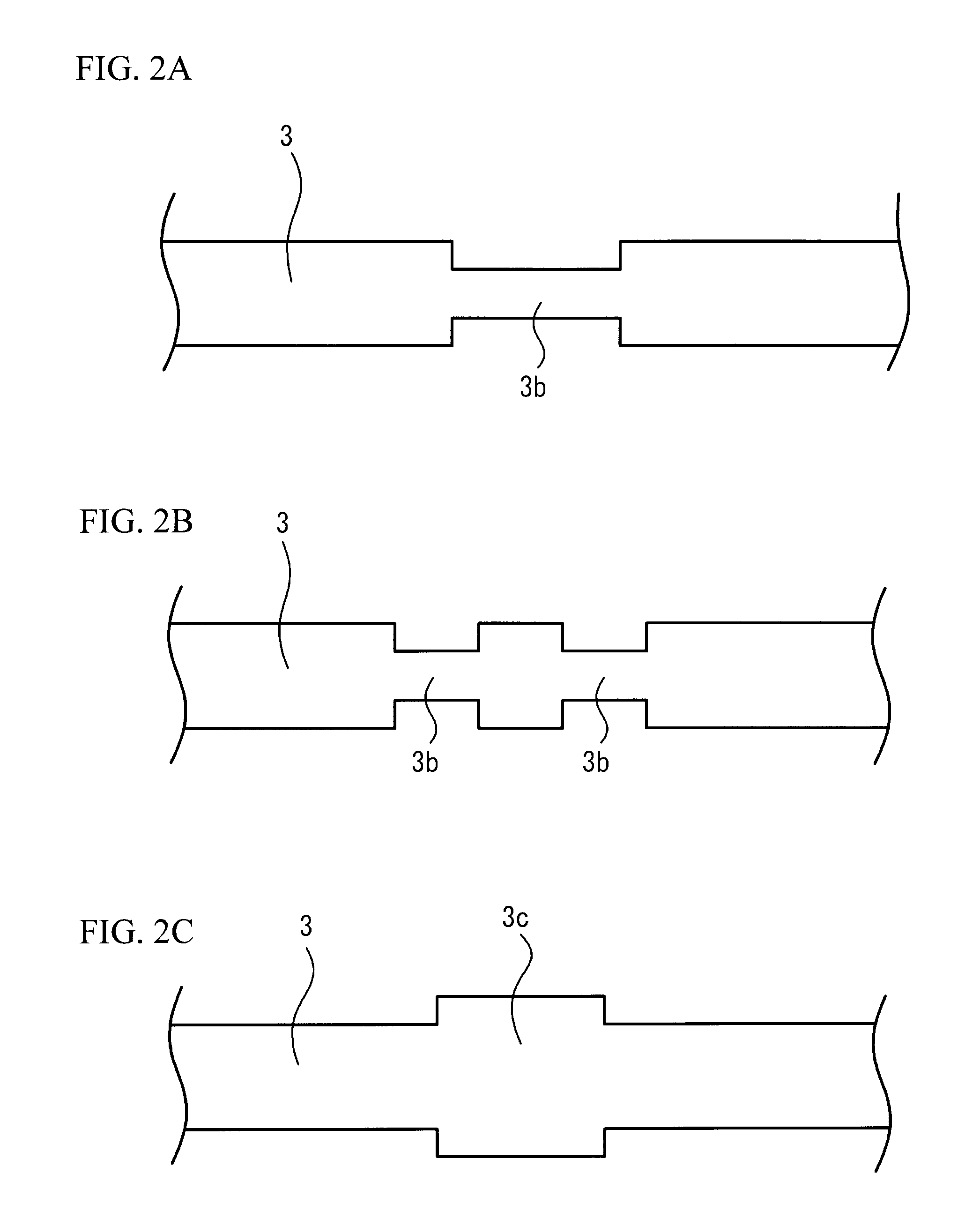
[0057]In the first embodiment and the second embodiment, the uniform active layer 3 is provided in the SG-DFB region A. The active layer 3 may include a plurality of waveguides in a resonator direction of which equivalent refraction index is tunable. Typically, the waveguides do not have a gain. The waveguides may be made of the same material as the optical waveguide layer 4 of the CSG-DBR region B. A heater for tuning the equivalent refraction index may be provided above the waveguides. An electrode for providing an electrical current may be provided instead of the heater. The waveguide and the active layer 3 may be alternately arranged in each segment of the SG-DFB region A. The waveguide may extend from one segment to another segment adjacent to the one segment. It is possible to achieve a detailed frequency control of an oscillation wavelength (Fine Tuning) by controlling the equivalent refraction index of the waveguide instead of temperature changing of the SG-DFB region A.
[005...
first modified embodiment
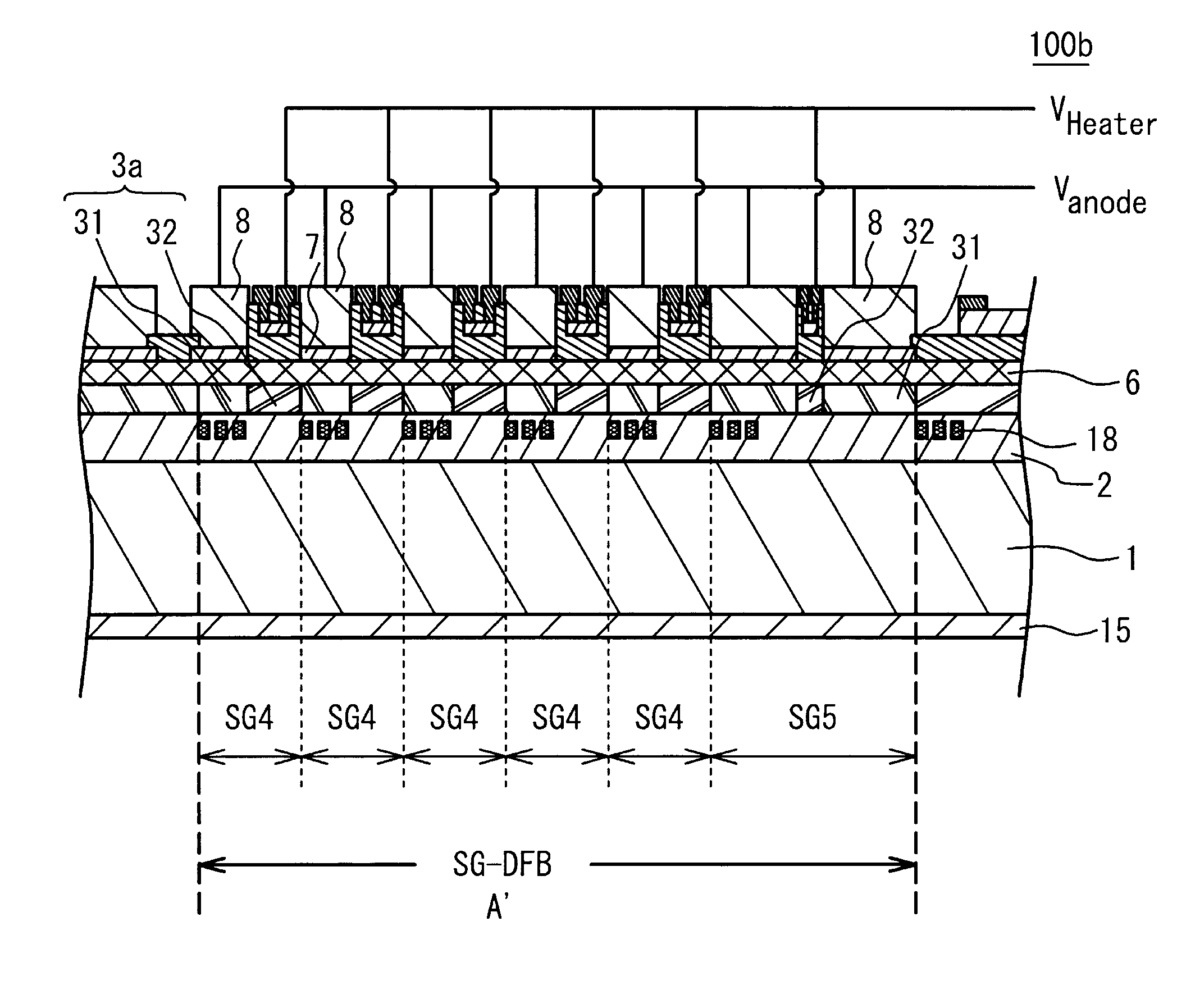
[0070]As illustrated in FIG. 8, the power supply electrode 23 of each heater 22 may be connected to power supplies that are independent from each other. In this case, it is possible to independently control the heater 22 of the long-segment SG5 and the hater 22 of the short-segment SG4. A next formula is obtained from the above-mentioned formulas.
ΔT∝LSG / Ltune·Δλ
[0071]It is preferable that the length of the passive waveguide 32 is enlarged in proportion to the length of the segment, in order to equalize the changing amount of temperature of the short-segment SG4 and the long-segment SG5. It is therefore preferable that the length of the passive waveguide 32 and the heater 22 of the long-segment SG5 is approximately 160 μm when the length of the passive waveguide 32 and the heater 22 of the five short-segments SG4 is approximately 80 μm. The length of the diffraction grating region of the short-segment SG4 and the long-segment SG5 is approximately 4 μm. The other structure is the same...
PUM
 Abstract
Description
Claims
Application Information
 - R&D
- Intellectual Property
- Life Sciences
- Materials
- Tech Scout
- Unparalleled Data Quality
- Higher Quality Content
- 60% Fewer Hallucinations
Browse by: Latest US Patents, China's latest patents, Technical Efficacy Thesaurus, Application Domain, Technology Topic, Popular Technical Reports.
© 2025 PatSnap. All rights reserved.Legal|Privacy policy|Modern Slavery Act Transparency Statement|Sitemap|About US| Contact US: help@patsnap.com


