Stator teeth, stator, rotating electric machine, and method for controlling rotating electric machine
a technology of stators and electric machines, applied in the direction of motor/generator/converter stoppers, dynamo-electric converter control, magnetic circuit shape/form/construction, etc., can solve the problems of weakened magnetic flux of magnets, inability to apply electric current through coils,
- Summary
- Abstract
- Description
- Claims
- Application Information
AI Technical Summary
Benefits of technology
Problems solved by technology
Method used
Image
Examples
first embodiment
The First Embodiment
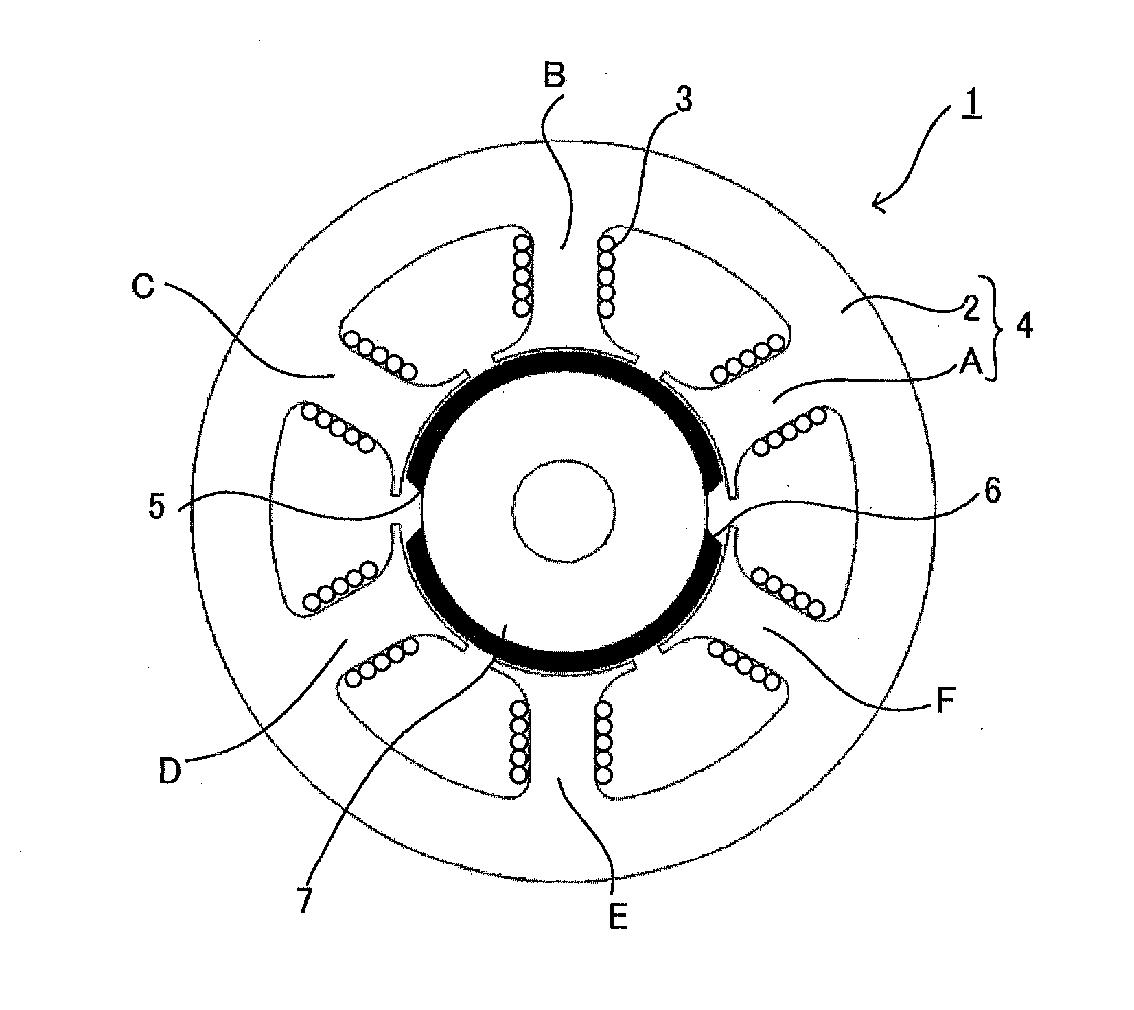
[0078]FIG. 1 shows a construction of a permanent magnet synchronous motor with two poles (a pair of poles) and six slots (the number of stator teeth: six) of the first embodiment of the present invention. As shown in FIG. 1, the permanent magnet synchronous motor 1 has a stator 4 which comprises: a stator yoke 2 made of silicon steel sheet or the like; and six pieces of stator teeth A, B, C, D, E, and F which are also made of silicon steel sheet so as to be formed integrally with the stator yoke 2 or formed in a fixable manner to the stator yoke 2. And, inside the six pieces of the stator teeth A, B, C, D, E and F, a rotor 7 is provided in a rotatable manner, the rotor 7 having permanent magnets with N pole 5 and S pole 6 in the outer circumference portion of the rotor 7.
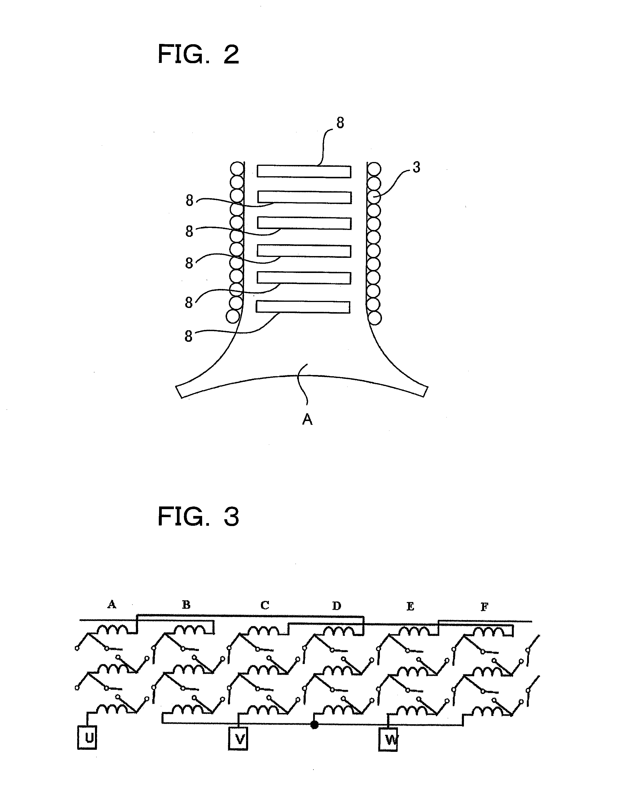
[0079]Around each of the six pieces of stator teeth A to F, three coils 3 are wound. FIG. 2 is a diagram showing a construction of one single stator tooth A. As shown in FIG. 2, to one single sta...
second embodiment
The Second Embodiment
[0097]FIG. 12 is a connection diagram of concentrated winding coils connected in parallel in the second embodiment of the present invention. As one example, the connection state of only the U phase is shown. In this example, the switches 8 are provided to both end portions of three coils 3 of each of the stator teeth A to F, and all of the both end portions of the three coils 3 are connected. As a result of that, the coils 3 become a state of concentrated winding coils connected in parallel.
[0098]In a case that the state of coils 3 is made into the concentrated winding coils connected in parallel in this way, as the induced voltage becomes one sixth in comparison with a case of concentrated winding coils connected in series shown in FIG. 4, driving with further higher speed is possible. The current to be applied to a coil is determined depending on a diameter of the coil. However, in this case, as it is possible to apply current six times as much as the case of ...
third embodiment
The Third Embodiment
[0100]FIG. 13 shows a construction of a three-phase inverter for motor driving, and
[0101]FIG. 14 shows switching patterns of a 120-degree current supply system as a simple example of driving the inverter shown in FIG. 13. In the third embodiment of the present invention is, as shown in FIG. 15, functions of the inverter are realized by turning on and off the switches 8 without providing the inverter to the outer portion of the motor 1.
[0102]Specifically, as shown in FIG. 16, one end of phase U consisting of a third coil 3 of the stator tooth A, a second coil 3 of the stator tooth B, and a first coil 3 of the stator tooth C is connected with a plus terminal. The other end of the first coil of the stator tooth C is connected with a neutral point. Further, one end of the phase V consisting of a third coil 3 of the stator tooth E, a second coil 3 of the stator tooth F, and a first coil 3 of the stator tooth A is connected with a minus terminal.
[0103]In this connectio...
PUM
 Abstract
Description
Claims
Application Information
 - R&D
- Intellectual Property
- Life Sciences
- Materials
- Tech Scout
- Unparalleled Data Quality
- Higher Quality Content
- 60% Fewer Hallucinations
Browse by: Latest US Patents, China's latest patents, Technical Efficacy Thesaurus, Application Domain, Technology Topic, Popular Technical Reports.
© 2025 PatSnap. All rights reserved.Legal|Privacy policy|Modern Slavery Act Transparency Statement|Sitemap|About US| Contact US: help@patsnap.com


