
Manufacturing Process for Aerospace Bearing Rolling Elements

a technology of aerospace bearings and manufacturing processes, applied in the field of bearings, can solve the problems of reducing the fatigue capacity and life of components, cyclic flexure, compressive and secondary tensile stresses, and localized maximum stresses are particularly severe, and achieve the effect of improving the fatigue/endurance limit of rolling conta

Active Publication Date: 2013-11-21
RAYTHEON TECH CORP +1
View PDF4 Cites 7 Cited by
  • Summary
  • Abstract
  • Description
  • Claims
  • Application Information

AI Technical Summary

Benefits of technology

The patent describes a method that improves the lifespan of bearing rolling elements and rings by increasing rolling contact fatigue / endurance limit and forming ultra-hard surfaces with high compressive residual stress. This enhances the performance and durability of the bearing components.

Problems solved by technology

When running in operation under load, the metal of the bearing rolling elements is subjected to stresses of enormous intensity, which will cause cyclic flexure, compressive and secondary tensile stresses, and sliding of different contacting surfaces.
It may cause deformation under extreme conditions.
Over the course of the life of a bearing, the alternating rolling contact fatigue stresses may happen at a given stress volume in the rolling element many millions of times. In addition, because of the very small contact area (compared to cylindrical or conical rolling elements) between the rolling element and the races, the localized maximum stresses are especially severe.
On the other hand, tensile residual stress in the surface of the component is detrimental since it is additive to the operational stress, thereby decreasing the component's fatigue capacity and life.
While effective to a point, it simply does not meet the increased property requirements of high performance bearings into the future.

Method used


Image

  • Manufacturing Process for Aerospace Bearing Rolling Elements
  • Manufacturing Process for Aerospace Bearing Rolling Elements
  • Manufacturing Process for Aerospace Bearing Rolling Elements

Examples


Embodiment Construction

[0029]As indicated above, the life of bearings plays an important role in the design constraints of modern aerospace engines. The inventors have found that the life of bearings is determined primarily by spatting (i.e., the detachment of material following the initiation of cracks at or below the contact surface), due to distress caused by surface roughness, corrosion, nicks, dents, debris ingestion or inadequate lubrication. The spalling may occur on the surface of a bearing rolling element and / or a bearing ring.

[0030]Another type of distress, known as rolling contact fatigue (RCF) can be defined as crack propagation caused by the near-surface alternating stress within the rolling-contact bodies, which eventually leads to material removal, i.e. spalling. It is a common type of failure encountered in bearings, even those which are well lubricated. One possible cause of such distress is the near-surface plastic deformation which leads to microcracks, grown or connected by a fatigue m...


PUM

PropertyMeasurementUnit
Temperatureaaaaaaaaaa
Lengthaaaaaaaaaa

Abstract

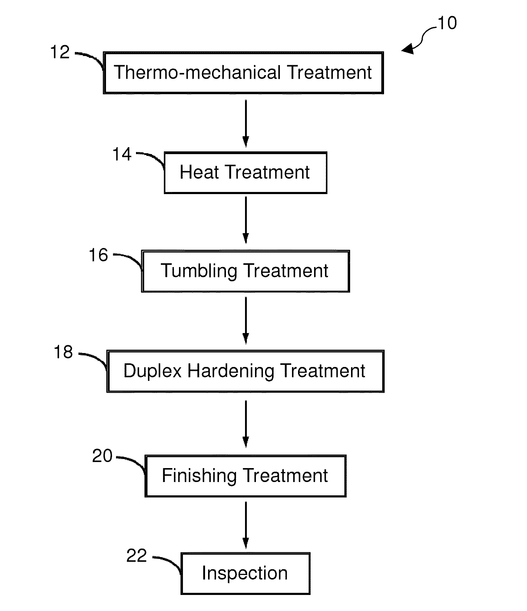
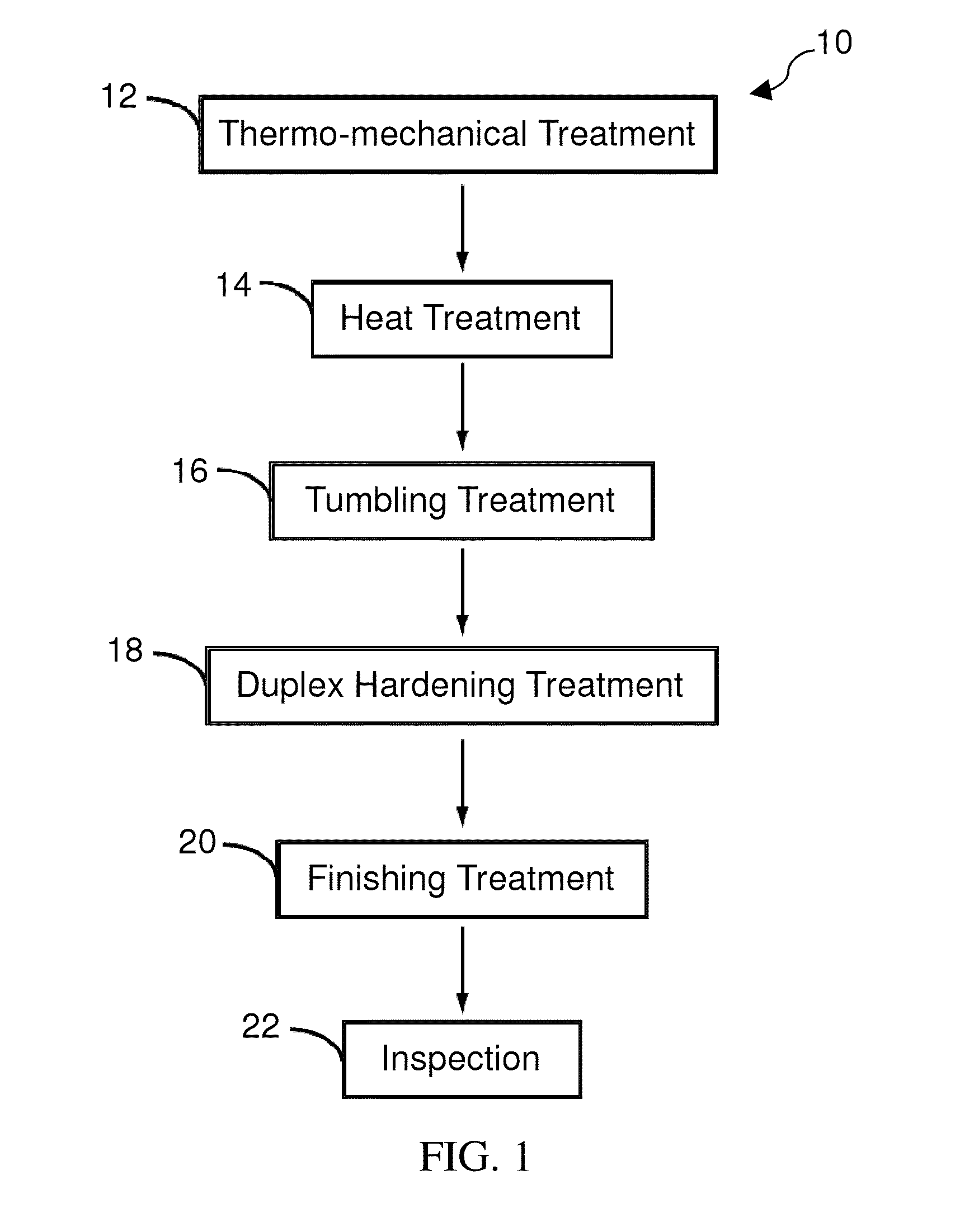
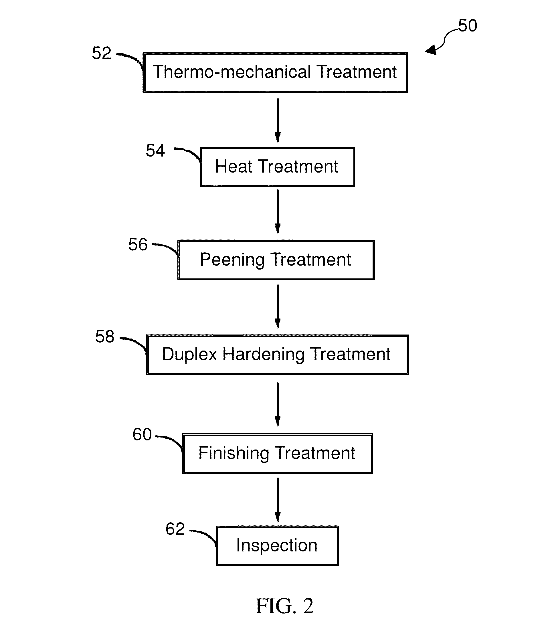
A method of treating bearing rolling elements or bearing rings after a hardening and temper heat treatment is disclosed. The method may include treating the bearing rolling elements in a tumbling treatment and then in a duplex hardening treatment. The method may include treating the bearing rings in a peening treatment and then in a duplex hardening treatment. The duplex hardening treatment may also include at least one sequential process segment consisting of subjecting the bearing rolling element & rings to a nitriding process to increase the surface hardness and compressive residual stress. The combined two-step process produces a deep surface / sub-surface residual stress greater than the depth of the maximum operating von-Mises shear stress along with an ultra-hard surface with high magnitude of compressive residual stress. In so doing, the bearing ring and rolling elements will have significantly enhanced rolling contact fatigue resistance and resistance to surface imperfections and debris.

Description

FIELD OF THE DISCLOSURE[0001]The present disclosure generally relates to bearings and, more particularly, relates to a process for manufacturing high performance rolling elements and bearing rings for aerospace bearing applications.BACKGROUND OF THE DISCLOSURE[0002]Metallic rolling elements for aerospace bearing applications are typically made of specific materials and according to an exacting set of process steps. For example, they are often made of AISI 52100 or M50 steels and are subject to the prescriptive steps of (a) thermo and / or mechanical processing to control the shape and size of the rolling elements and rings; (b) heat treatment comprised of austenitizing, quenching, cold treating, and tempering to develop the desired hardness, compressive stress, fracture toughness and surface residual stress profile; (c) abrasive machining according to specification requirements; and (d) non-destructive inspection for quality assurance. The above prescriptive practices have evolved ove...

Claims


Application Information

Patent Timeline
IPC IPC(8): C23C8/02C21D7/06
CPCB24B1/00B24B11/02B24B19/06B24B31/02C21D1/76C21D7/06C21D9/36C21D9/40C23C8/02C23C8/26C23C8/36C23C8/50C23C8/80F16C33/32F16C2223/02F16C2223/10F16C2240/18F16C2360/23Y10T29/47Y02P10/20
Inventor CHIN, HERBERT A.OGDEN, WILLIAM P.HALUCK, DAVID A.MCCUTCHAN, SEANSPITZER, RONALD F.KELLER, ALLEN V.
Owner RAYTHEON TECH CORP
Learn More