Graphite crucible for single crystal pulling apparatus and method of manufacturing same

Inactive Publication Date: 2013-11-21
TOYO TANSO KK
View PDF3 Cites 5 Cited by
  • Summary
  • Abstract
  • Description
  • Claims
  • Application Information

AI Technical Summary

Benefits of technology

The present invention relates to a method that prevents the reaction between temperature-controlled gases and the surface of a graphite crucible substrate. This is achieved by carbonizing the surface of the substrate and filling the open pores with a pyrocarbon material. This results in a longer service life for the graphite crucible as it prevents the development of silicon carbide (SiC) formation on the surface.

Problems solved by technology

However, the quartz crucible softens at high temperature and is insufficient in strength.
Accordingly, when such a heat treatment is carried out repeatedly, the graphite crucible is gradually turned into SiC, so that the dimensions of the graphite crucible may be changed, or the graphite crucible may become brittle as a material and microcracks develop therein, causing the graphite crucible to break in the end.

Method used


Image

  • Graphite crucible for single crystal pulling apparatus and method of manufacturing same
  • Graphite crucible for single crystal pulling apparatus and method of manufacturing same
  • Graphite crucible for single crystal pulling apparatus and method of manufacturing same

Examples


embodiment 1

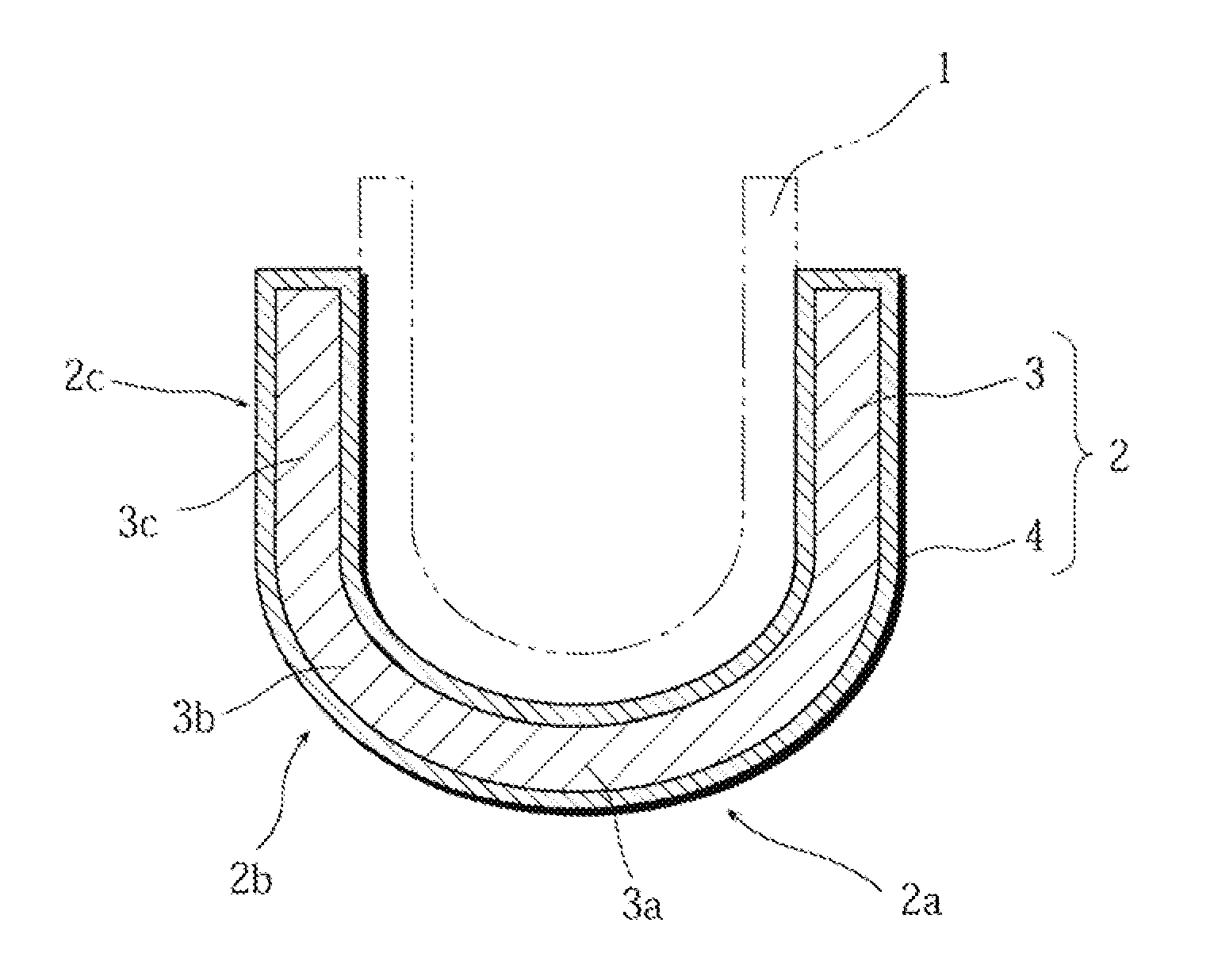
[0065]FIG. 1 is a vertical cross-sectional view for illustrating one example of a graphite crucible for single crystal pulling apparatus according to Embodiment 1. A graphite crucible 2 for retaining a quartz crucible 1 includes a graphite crucible substrate 3 as a graphite crucible forming material, and a coating film 4 made of a carbonized phenolic resin and formed over the entire surface of the graphite crucible substrate 3 (hereinafter the coating film may also be referred to simply as a “phenolic resin coating film”). The graphite crucible substrate 3 used here should have a bulk density of 1.70 Mg / m3 or higher, a flexural strength of 30 MPa or higher, and a Shore hardness of 40 or higher as its characteristics, in order to ensure necessary mechanical strength for a crucible and also taking into consideration readiness of the phenolic resin impregnation. The carbonized substance that constitutes the coating film 4 may be a graphitized substance the entirety or a portion of whic...

embodiment 2

[0078]FIG. 4 is a vertical cross-sectional view for illustrating one example of a graphite crucible for single crystal pulling apparatus according to Embodiment 2. A graphite crucible 2 for retaining a quartz crucible 1 includes a graphite crucible substrate 3 as a graphite crucible forming material, and a pyrocarbon coating film 4A formed over the entire surface of the graphite crucible substrate 3. The graphite crucible substrate 3 used here should have a bulk density of 1.65 Mg / m3 or higher, a flexural strength of 30 MPa or higher, and a Shore hardness of 40 or higher as its characteristics, in order to ensure necessary mechanical strength for a crucible and also taking into consideration readiness of the deposition of pyrocarbon.

[0079]Here, the shape of the graphite crucible 2 is generally in a cup-like shape, formed by a bottom portion 2a, a curved portion (sharply curved portion) 2b curved upward and connected to the bottom portion 2a, and a straight trunk portion 2c extending...

examples

[0086]Hereinbelow, the present invention will be described in detail by examples. It should be noted that the present invention is in no way limited to the following examples.


PUM

PropertyMeasurementUnit
Temperatureaaaaaaaaaa
Thicknessaaaaaaaaaa
Thicknessaaaaaaaaaa

Abstract

A graphite crucible (2) for retaining a quartz crucible (1) has a graphite crucible substrate (3) as a graphite crucible forming material, and a coating film (4) made of a carbonized phenolic resin and formed over the entire surface of the graphite crucible substrate (3). The phenolic resin is impregnated inside open pores (5) existing in a surface of the graphite crucible substrate (3). The coating film (4) may be formed only within a portion of the graphite crucible in which SiC formation can occur easily, not over the entirety of the surface of the graphite crucible. For example, it is possible to deposit the film only on the entire inner surface of the crucible. It is also possible to deposit the film only on a curved portion (sharply curved portion) of the inner surface, or only on a curved portion and a straight trunk portion.

Description

TECHNICAL FIELD[0001]The present invention relates to a carbon crucible used for retaining a quartz crucible used in an apparatus for pulling a single crystal of silicon or the like by a Czochralski process (hereinafter referred to as a “CZ process”), and to a method of manufacturing the same.BACKGROUND ART[0002]Single crystals of silicon or the like used for manufacturing ICs and LSIs are usually manufactured by a CZ process. The CZ process is as follows. Polycrystalline silicon is put in a high-purity quartz crucible, and while rotating the quartz crucible at a predetermined speed, the polycrystalline silicon is heated by a heater to melt the polycrystalline silicon. A seed crystal (silicon single crystal) is brought into contact with the surface of the melt, and is gradually pulled up while being rotated at a predetermined speed to solidify the polycrystalline silicon melt, whereby a silicon single crystal is grown.[0003]However, the quartz crucible softens at high temperature an...

Claims


Application Information

Patent Timeline
IPC IPC(8): C30B15/10
CPCC30B15/10C04B35/6269C04B2235/95C04B2235/96C30B35/002C04B41/85C04B41/009C04B41/5001C04B35/521C04B35/522C04B2235/616C04B2235/77C30B29/06Y10T117/1032C04B41/4535C04B41/4554C04B41/457C04B41/4572C04B41/87C30B15/00C30B15/20
Inventor OKADA, OSAMUHIROSE, YOSHIAKIYOKOI, TOMOMITSUOGITA, YASUHISA
Owner TOYO TANSO KK
Why Eureka
Try Eureka