Workpiece dividing method

a technology of dividing method and workpiece, which is applied in the direction of manufacturing tools, metal working equipment, welding/soldering/cutting articles, etc., can solve the problems of insufficient production, etc., and achieves the reduction of the increase of the amount of debris generated, and the effect of reducing the width of the area to be divided by laser processing

Active Publication Date: 2013-11-14
DISCO CORP
View PDF21 Cites 7 Cited by
  • Summary
  • Abstract
  • Description
  • Claims
  • Application Information

AI Technical Summary

Benefits of technology

The present invention is a method for dividing a securely sized workpiece into smaller chips. The method includes preparing the workpiece, holding it on a table, and using a cutting blade to create a shallow cut on the workpiece surface. A laser beam is then applied along the cut to complete the division. This method reduces the width of the area being processed and minimizes debris exposure during the process. It achieves a more efficient and secure method for dividing workpieces.

Problems solved by technology

However, in the case of applying a laser beam to the workpiece to form a laser processed groove on the front side of the workpiece, debris as fused matter generated from the workpiece by the laser beam is deposited on the opposite sides of the laser processed groove according to the amount of removal from the workpiece by the laser beam.
As a result, it may not be possible to sufficiently obtain the advantage that the width of an area to be divided by laser processing can be reduced.

Method used


Image

  • Workpiece dividing method
  • Workpiece dividing method
  • Workpiece dividing method

Examples


Embodiment Construction

[0015]A workpiece dividing method according to a preferred embodiment of the present invention will now be described in detail with reference to the drawings. The present invention is not limited to this preferred embodiment. The composing elements in this preferred embodiment may include those that can be easily assumed by persons skilled in the art or substantially the same as those known in the art.

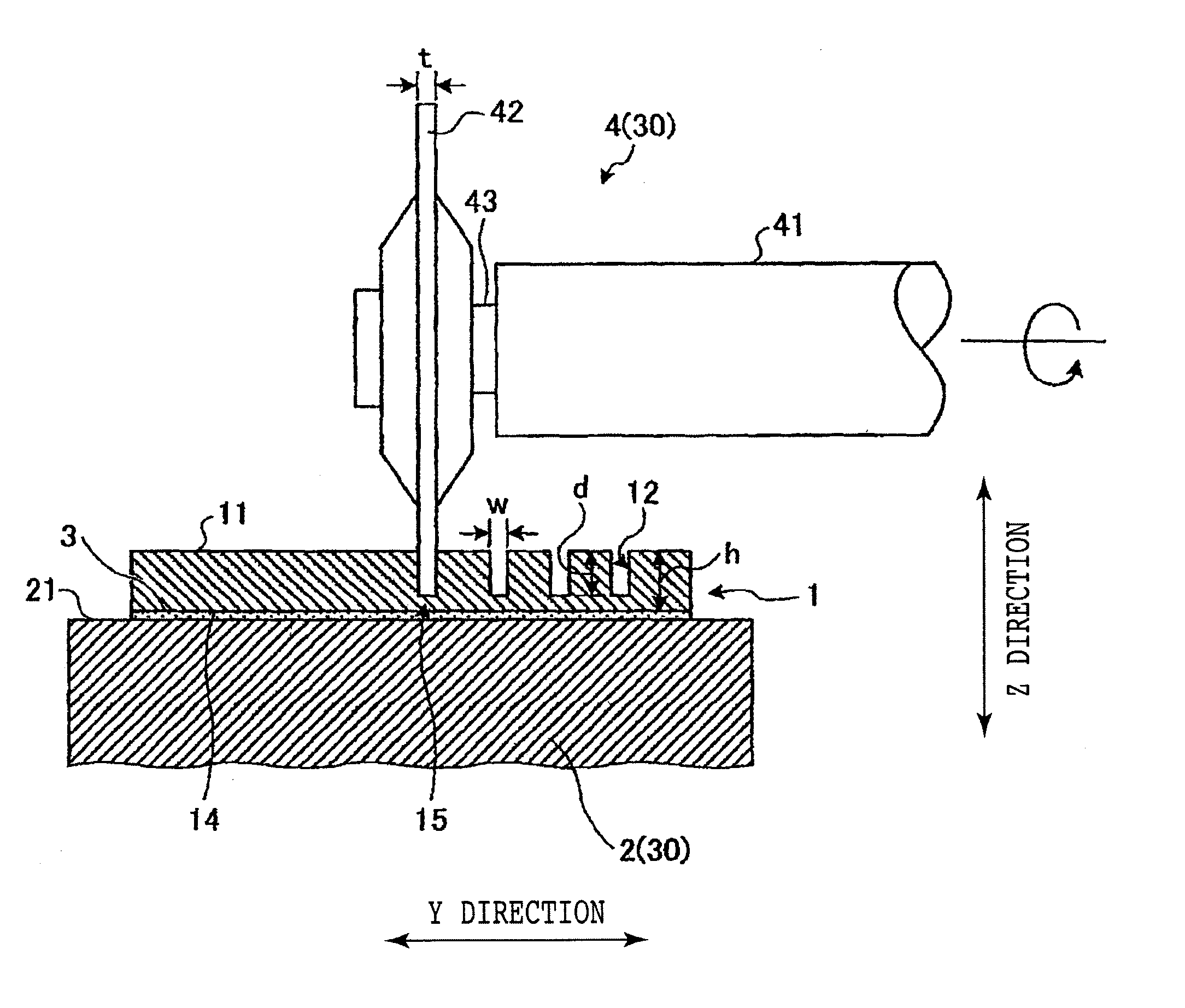
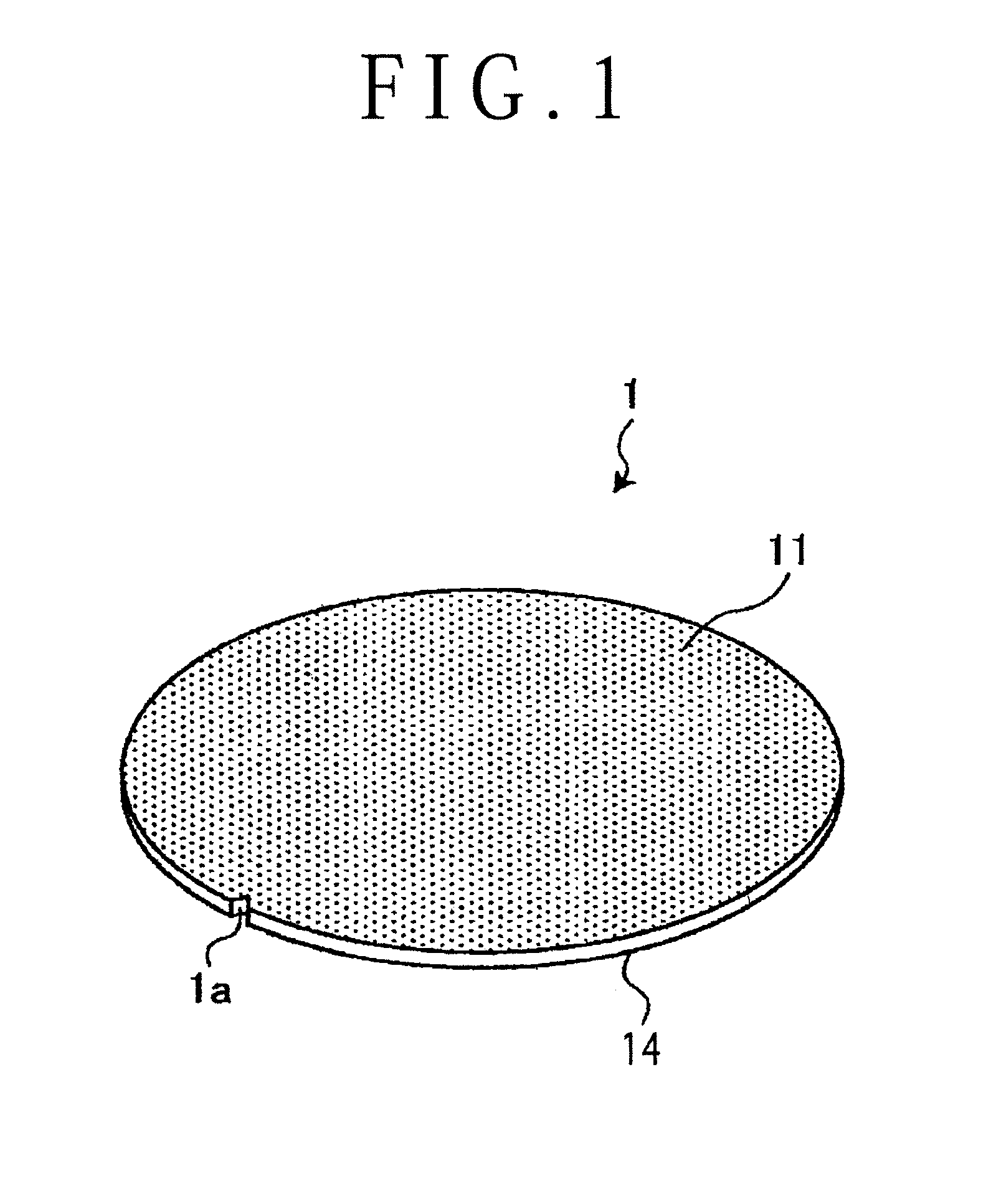
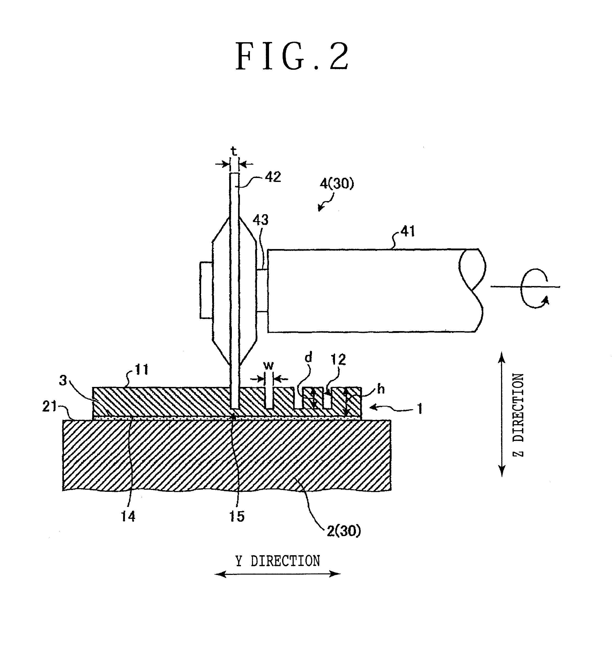
[0016]The preferred embodiment will now be described with reference to FIGS. 1 to 3. The preferred embodiment relates to a workpiece dividing method. FIG. 1 is a perspective view of a workpiece 1 to be divided by the workpiece dividing method according to the preferred embodiment, FIG. 2 is a sectional side view for illustrating a cut groove forming step in the workpiece dividing method according to the preferred embodiment, and FIG. 3 is a sectional side view for illustrating a laser cutting step in the workpiece dividing method according to the preferred embodiment. As shown in FIG. ...


PUM

PropertyMeasurementUnit
surface roughness Raaaaaaaaaaa
surface roughnessaaaaaaaaaa
thicknessaaaaaaaaaa

Abstract

A workpiece dividing method for dividing a platelike workpiece into a plurality of individual chips. The workpiece dividing method includes a workpiece preparing step of preparing the platelike workpiece, at least one side of the workpiece being formed as a mat surface, a holding step of holding the workpiece on a holding surface of a chuck table in the condition where the mat surface of the workpiece is exposed, a cut groove forming step of cutting the mat surface of the workpiece held on the holding surface of the chuck table by using a cutting blade to thereby form a cut groove with a remaining portion, and a laser cutting step of applying a laser beam to the workpiece along the cut groove to thereby cut the remaining portion.

Description

BACKGROUND OF THE INVENTION[0001]1. Field of the Invention[0002]The present invention relates to a workpiece dividing method.[0003]2. Description of the Related Art[0004]A wafer having semiconductor devices such as ICs and LSIs or optical devices such as LDs and LEDs formed on the front side is divided by applying a laser beam along division lines with a laser processing apparatus to form laser processed grooves on the front sides of the wafer, thereby obtaining individual devices to be used as memories, CPUs, LEDs, etc. (see Japanese Patent Laid-Open No. Hei 10-305420, for example). Such a method using a laser beam to form a laser processed groove has an advantage such that the width of an area to be processed in dividing the wafer can be reduced as compared with the case of cutting the wafer by using a cutting blade. Accordingly, in the case of manufacturing a device chip having a small size, it is possible to increase the number of chips that can be produced from one wafer as a w...

Claims


Application Information

Patent Timeline
Patent Type & Authority Applications(United States)
IPC IPC(8): B26D9/00B23K26/42B23K26/36
CPCB23K26/0093B23K26/4075H01L33/0095B23K26/421B26D9/00B23K26/367B23K26/364B23K26/60B23K26/40Y10T83/0215B23K2103/50
Inventor KUMAZAWA, SATOSHI
Owner DISCO CORP
Why Eureka
Try Eureka