
Brake Monitoring System for an Air Brake Arrangement

a technology of air brake and monitoring system, which is applied in the direction of braking system, analogue process for specific applications, instruments, etc., can solve the problems of complex and costly solutions of arrangemen

Active Publication Date: 2013-11-07
WABTEC HLDG CORP
View PDF8 Cites 36 Cited by
  • Summary
  • Abstract
  • Description
  • Claims
  • Application Information

AI Technical Summary

Benefits of technology

The patent text describes a brake monitoring system and an air brake arrangement for vehicles, particularly trains. The system includes sensors to measure air pressure in components of the brake arrangement, a controller to determine data such as air pressure over time, air leakage, and brake holding prediction, and a communication device to transmit the data to a remote or central controller, vehicle controller, or other system. The system can help improve the efficiency and reliability of braking systems for vehicles.

Problems solved by technology

While some potential solutions may involve locking schemes in the brake cylinder BC and powered hand brakes, such arrangements represent complex and costly solutions.

Method used


Image

  • Brake Monitoring System for an Air Brake Arrangement
  • Brake Monitoring System for an Air Brake Arrangement
  • Brake Monitoring System for an Air Brake Arrangement

Examples


Embodiment Construction

[0023]It is to be understood that the invention may assume various alternative variations and step sequences, except where expressly specified to the contrary. It is also to be understood that the specific devices and processes illustrated in the attached drawings, and described in the following specification, are simply exemplary embodiments of the invention.

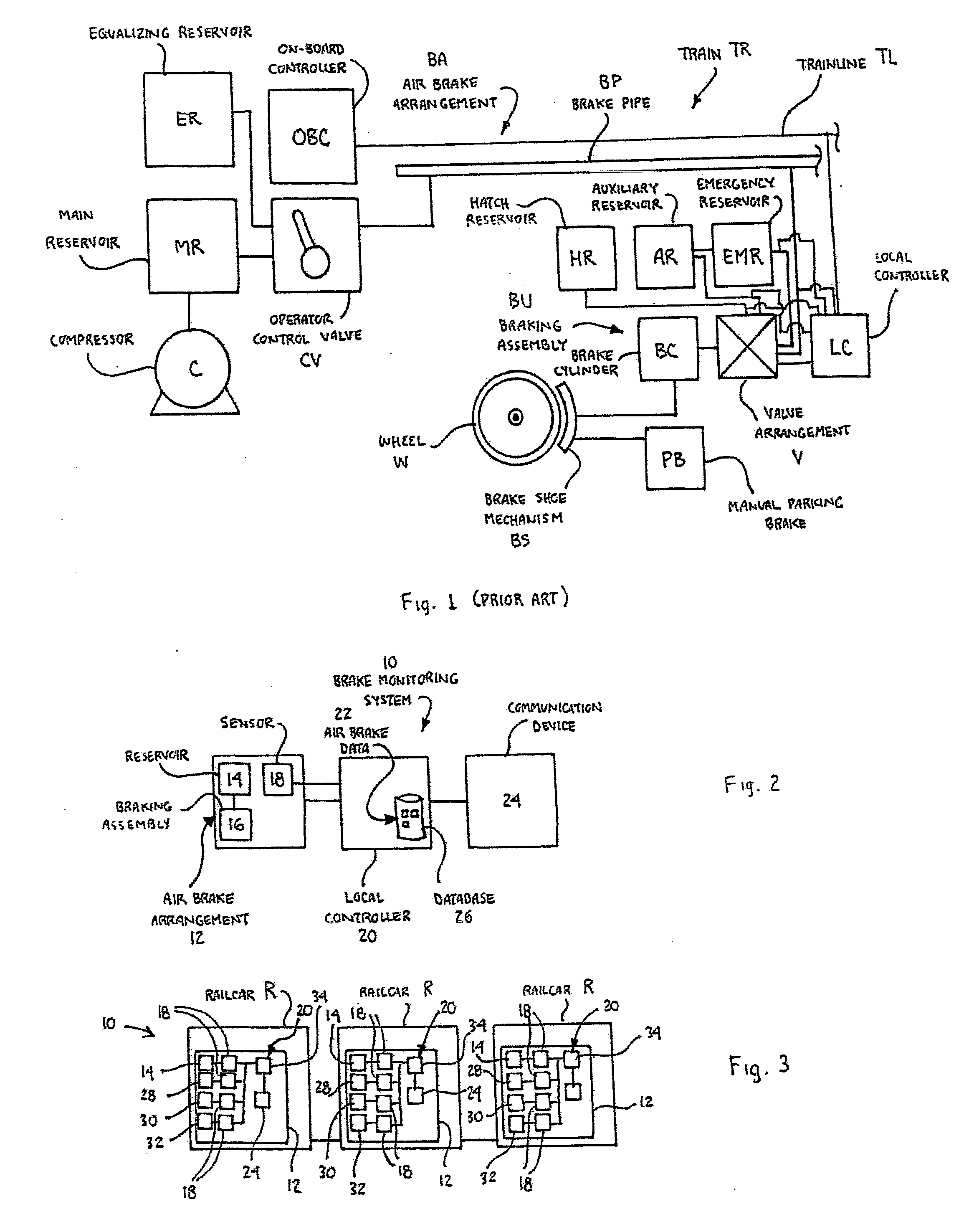
[0024]According to one preferred and non-limiting embodiment of the present invention, provided is a brake monitoring system 10 and method for an air brake arrangement 12 used in connection with a railcar R, which is part of a consist making up a train TR. Certain preferred and non-limiting embodiments of the brake monitoring system 10 and air brake arrangement 12 are illustrated in schematic form in FIGS. 2-4.

[0025]It should be noted that while the system 10, method, and arrangement 12 of the present invention are specifically discussed herein with connection to a pneumatically-driven brake arrangement (air brakes) for a train...


PUM


Abstract

A brake monitoring system for an air brake arrangement including: at least one sensor to measure air pressure in at least one component of an air brake arrangement; at least one local controller to determine air brake data; and at least one communication device to transmit at least a portion of the air brake. An air brake arrangement and a computer-implemented method of determining air brake data in an air brake arrangement are also disclosed.

Description

BACKGROUND OF THE INVENTION[0001]1. Field of the Invention[0002]The present invention relates generally to brake monitoring systems and arrangements for use in connection with an air brake arrangement, and in particular to a brake monitoring system and an air brake arrangement for a train, railcar, railway vehicle, and similar vehicles, and preferably an electronically-controlled pneumatic air brake arrangement for a railway vehicle.[0003]2. Description of the Related Art[0004]As is known, braking systems and arrangements are required for slowing and stopping vehicles, such as cars, trucks, trains, railcars, railway vehicles, and the like. With specific respect to trains and other railway vehicles, the braking system is normally in the form of a pneumatically-driven arrangement (or “air brake arrangement”) having mechanisms and components that interact with each railcar. A known air brake arrangement BA is illustrated in schematic form in FIG. 1.[0005]With reference to FIG. 1, the o...

Claims


Application Information

Patent Timeline
IPC IPC(8): B60T17/22F16D66/00G06F11/30
CPCB60T7/18B60T13/665B60T17/228
Inventor KULL, ROBERT C.
Owner WABTEC HLDG CORP
Learn More