
Train brake control method and equipment

A braking control and train technology, applied to railway car body components, signal indicators on vehicles, railway signals and safety, etc., can solve problems such as wheel friction heat damage, increase braking force and reduce wheel abrasion Risk, effect of train speed reduction

Active Publication Date: 2020-04-03
ZHUZHOU ELECTRIC LOCOMOTIVE CO
View PDF5 Cites 9 Cited by
  • Summary
  • Abstract
  • Description
  • Claims
  • Application Information

AI Technical Summary

Problems solved by technology

[0004] However, if a certain emergency braking hard line loses power without disconnecting the train safety loop, only the BCU connected to the emergency braking hard line will trigger emergency braking, and only this BCU is located in the train The vehicle of the vehicle will perform emergency braking. At this time, the vehicle will be in a state of running with brakes, causing the wheels of the vehicle to be damaged due to excessive frictional heat

Method used


Image

  • Train brake control method and equipment
  • Train brake control method and equipment
  • Train brake control method and equipment

Examples


Embodiment Construction

[0043] Exemplary embodiments of the present invention will be described in more detail below with reference to the accompanying drawings. Although exemplary embodiments of the present invention are shown in the drawings, it should be understood that the invention may be embodied in various forms and should not be limited to the embodiments set forth herein. Rather, these embodiments are provided for more thorough understanding of the present invention and to fully convey the scope of the present invention to those skilled in the art.

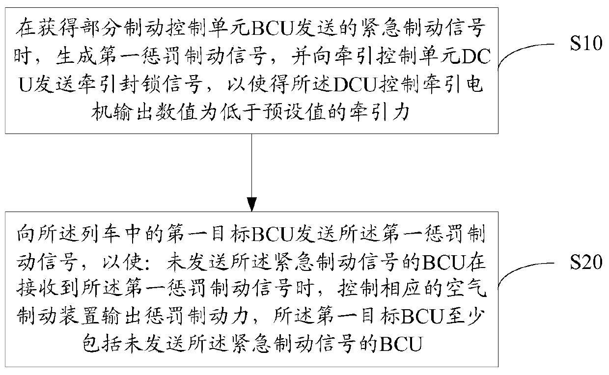
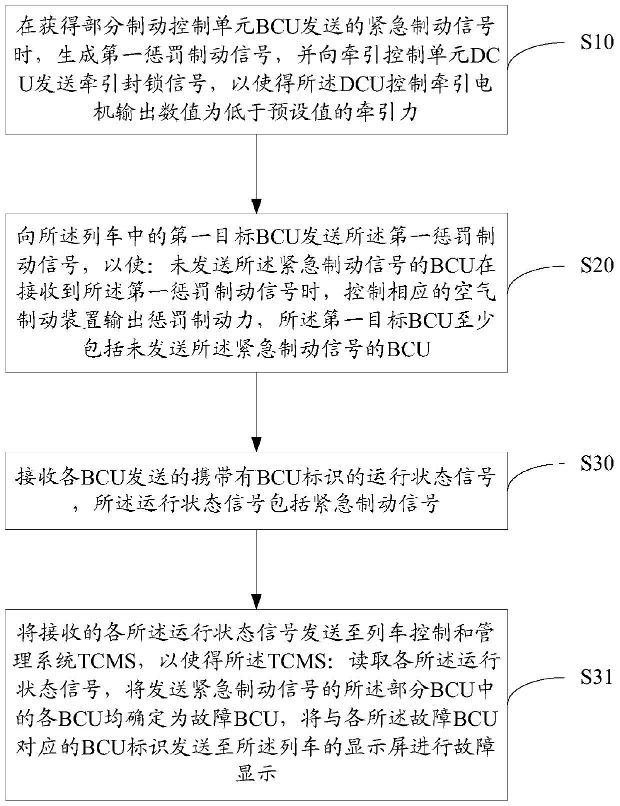
[0044] like figure 1 As shown, the present embodiment proposes a train braking control method, which may include the following steps:

[0045]S10. When obtaining the emergency braking signal sent by the partial braking control unit BCU, generate a first penalty braking signal, and send a traction blocking signal to the traction control unit (DCU, Drive Control Unit), so that the DCU controls the traction The output value of the motor is the tr...


PUM


Abstract

The invention discloses a train brake control method and equipment. The method comprises the following steps: when emergency brake signals sent by a part of brake control units BCU are acquired, generating a first punishment brake signal, sending a traction blocking signal to a traction control unit DCU so as to enable the DCU to control the traction motor to output traction force with the numerical value lower than a preset value; sending a first punishment braking signal to a first target BCU in the train; when the BCU which does not send the emergency brake signal receives the first punishment brake signal, controlling the corresponding air braking device to output punishment braking force, wherein the first target BCU at least comprises a BCU which does not send an emergency braking signal, The braking force of the whole train in a non-traction running state can be increased, and the deceleration of the train is increased, so that the high friction force and high loss of the wheelsof the vehicle subjected to accidental emergency braking can be quickly dispersed to the wheels of other vehicles, the high friction force and high loss of the local wheels of the train are reduced,and the wheel scratching risk is reduced.

Description

technical field [0001] The invention relates to the field of train braking control, in particular to a train braking control method and equipment. Background technique [0002] With the development of train control technology, the train brake control technology has been continuously improved. [0003] The train is composed of multiple vehicles, and the vehicles can be divided into two types, one is a motor vehicle that provides traction, and the other is a trailer driven by a passive vehicle. In the straight-through brake control system commonly used in trains, the bogie of each vehicle is equipped with a brake control unit (BCU, Brake control unit), and each of these BCUs is connected to the train safety loop through an emergency brake hard line . When the train enters the emergency braking condition, the train safety loop is disconnected, and each emergency braking hard line loses power. After each BCU detects that the connected emergency braking hard Braking, so that t...

Claims


Application Information

Patent Timeline
IPC IPC(8): B61L15/00
CPCB61L15/0018
Inventor 陈林段继超罗智迅王丽金怡
Owner ZHUZHOU ELECTRIC LOCOMOTIVE CO
Learn More