
Stent apparatus

Inactive Publication Date: 2013-11-07
KYOTO MEDICAL PLANNING
View PDF2 Cites 3 Cited by
  • Summary
  • Abstract
  • Description
  • Claims
  • Application Information

AI Technical Summary

Benefits of technology

The present invention relates to a stent apparatus that can be expanded by balloon inflation to a lesion site in a vessel. The invention aims to provide a stent apparatus that can be easily mounted and securely positioned on any one of balloons of various shapes and structures, regardless of the type of balloon catheter used. Additionally, the invention provides a stent apparatus that can hold a stent without preventing expansion by balloon inflation. The invention also allows for the administration of drugs to a living body by implanting them with a stent to prevent thrombosis and intimal proliferation.

Problems solved by technology

The stent disengaged from the balloon cannot be rapidly expanded in diameter with the balloon inflation force, making correct implantation to the intended site such as the lesion site impossible.

Method used


Image

  • Stent apparatus
  • Stent apparatus
  • Stent apparatus

Examples


Embodiment Construction

[0059]Referring to attached drawings, embodiments of the present invention is described hereinafter.

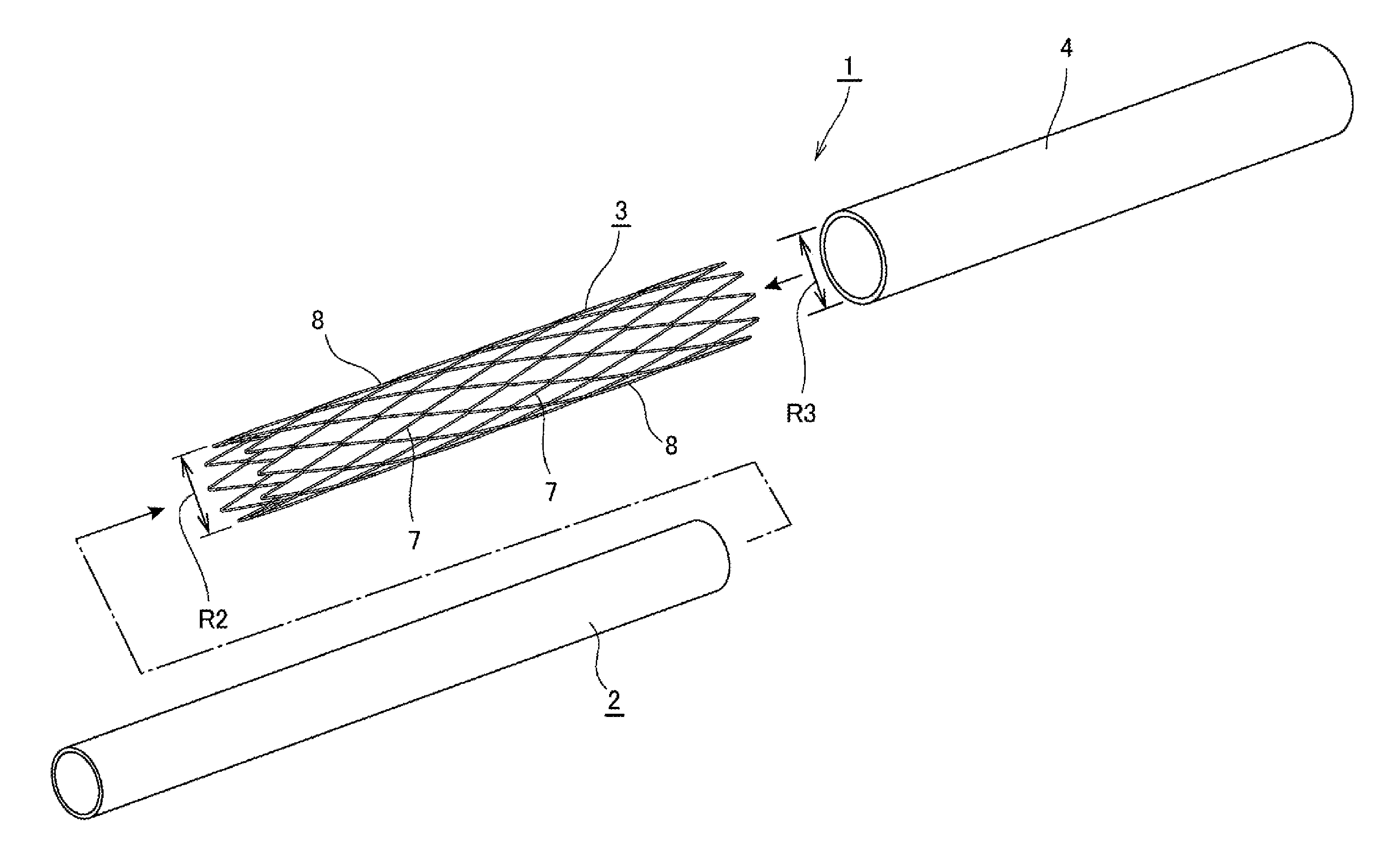
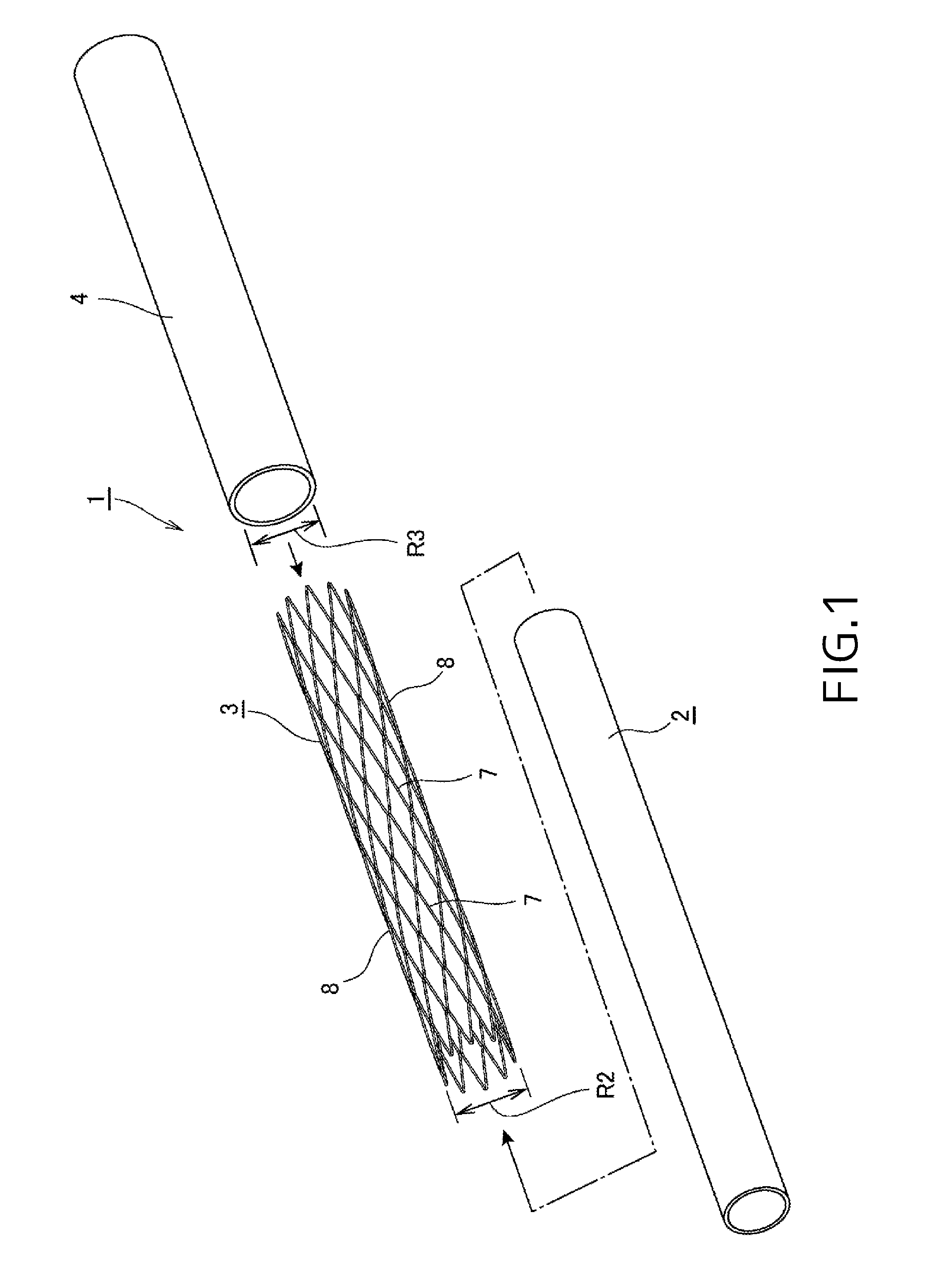
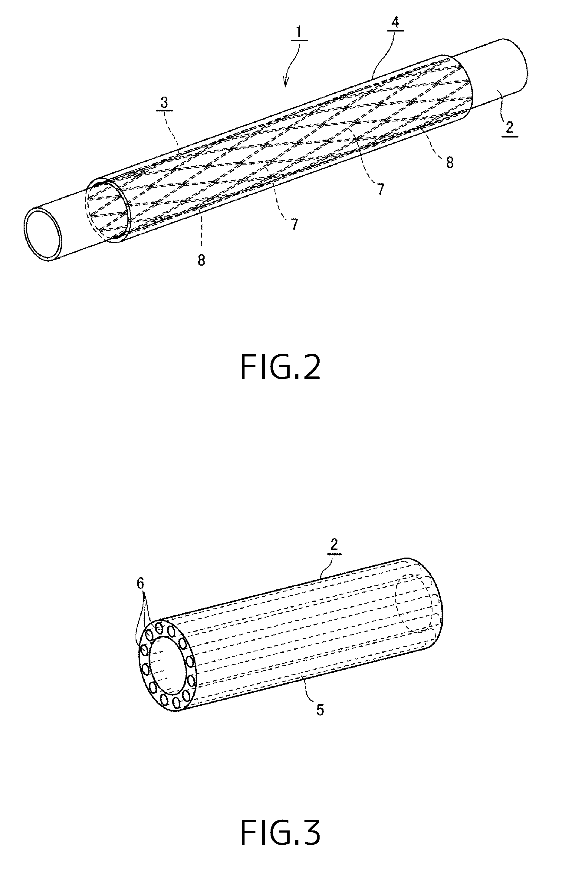
[0060]As shown in FIGS. 1 and 2, a stent apparatus 1 according to the present invention includes a tubular cartridge 2 having an appropriate length, a cylindrical stent 3 mounted on an outer surface of this tubular cartridge 2 and a stent covering member 4 covering outer side of the stent 3 to hold the stent 3.

[0061]The tubular cartridge 2 constituting the stent apparatus 1 of the present invention is preferably formed of a material easily expandable in radial direction and hardly expandable in axial direction. For example, this tubular cartridge 2 is formed by incorporating a strand 6 of a yarn having certain rigidity into a tube 5 having the expandability such that the strand 6 extends in axial direction. By employing this constitution, the strand 6 restricts the axial expansion of the tubular cartridge 2. Moreover, the tubular cartridge 2 easily expandable in radial direction and h...


PUM


Abstract

Present invention is a stent apparatus in which a stent to scaffold a vessel from the inside is held by a stent covering member comprising: a tubular cartridge expandable and contractible in radial direction, the expansion of which in axial direction orthogonal to the radial direction being restricted; a stent formed of a biodegradable polymer as a tubular shape, shape memorized to an expanded size larger than an inner diameter of a target blood vessel in which the stent is to be implanted, and mounted to the tubular cartridge in contracted state; and a stent covering member formed of a biodegradable polymer having elasticity as a cylindrical shape having an inner diameter to keep the stent in contracted state by holding an outer surface of the stent and, when the stent is expanded to the shape memorized shape, plastically deformed to release the holding of the stent.

Description

CROSS REFERENCE TO RELATED APPLICATIONS[0001]The present application is a National Stage of International Application No. PCT / JP2011 / 004049 filed Jul. 15, 2011 and which claims priority to Japanese Patent Application No. JP2010-163376 filed Jul. 20, 2010, the entire contents of which are being incorporated herein by reference.BACKGROUND[0002]This invention relates to a stent apparatus for holding a stent in contracted state with a stent covering member, wherein the stent is, when implanted into a vessel such as blood vessels, expanded in the diameter to scaffold the vessel from inside.BACKGROUND ART [0003]Heretofore, when stenosis occurs in a blood vessel, such as coronary artery, percutaneous transluminal coronary angioplasty (PTCA) employing stenting is performed in which the stenosed portion is expanded by using a medical balloon catheter, and a cylindrical stent is implanted into this expanded portion for scaffolding the vessel from inside so as to ensure the blood flow.[0004]St...

Claims


Application Information

Patent Timeline
IPC IPC(8): A61F2/82A61F2/07
CPCA61F2/82A61F2/07A61F2/90A61F2002/072A61F2002/9583A61F2/95A61L27/14
Inventor IGAKI, KEIJI
Owner KYOTO MEDICAL PLANNING
Learn More