
Method for remotely managing a sensor network topology and gateway

a sensor network and gateway technology, applied in the field of communication technologies, can solve the problems of not supporting remote topology management of a stub sensor network through the m2m gateway, unable to predict the working status of a device, and the above function cannot be implemented, so as to reduce the complexity

Active Publication Date: 2013-11-07
HUAWEI CLOUD COMPUTING TECH CO LTD
View PDF2 Cites 37 Cited by
  • Summary
  • Abstract
  • Description
  • Claims
  • Application Information

AI Technical Summary

Benefits of technology

The present invention offers a method for remotely managing a sensor network topology and gateway, which simplifies the process of managing a large number of sensors connected to a gateway. This is achieved by using a preconstructed topology and a uniform management interface consistent with existing remote device management technologies. This method reduces the complexity of managing a sensor network and helps in optimizing network efficiency.

Problems solved by technology

Because the stub sensor network generally performs networking in a self-organized manner, sometimes, it is difficult to predict a network topology and a working status of a device.
The technology can implement remote management for the M2M gateway through operating management object (Management Object, MO) data on the M2M gateway, but still does not support remote topology management for a stub sensor network through the M2M gateway.
The above function can only be implemented by further combining other ZigBee management commands, where the operation method is complicated.
Other sensor network protocols (for example, the BlueTooth) do not provide a method for remotely managing a topology through a gateway.
In the prior art, no solution is provided for remote topology management of a sensor network successive to an M2M gateway or the management is difficult and complicated.

Method used


Image

  • Method for remotely managing a sensor network topology and gateway
  • Method for remotely managing a sensor network topology and gateway
  • Method for remotely managing a sensor network topology and gateway

Examples


embodiment 1

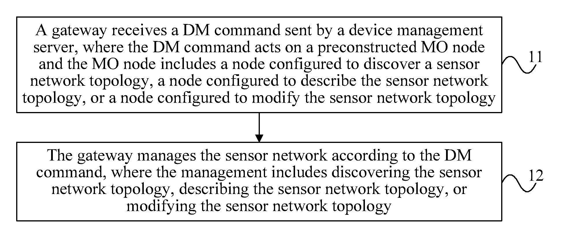
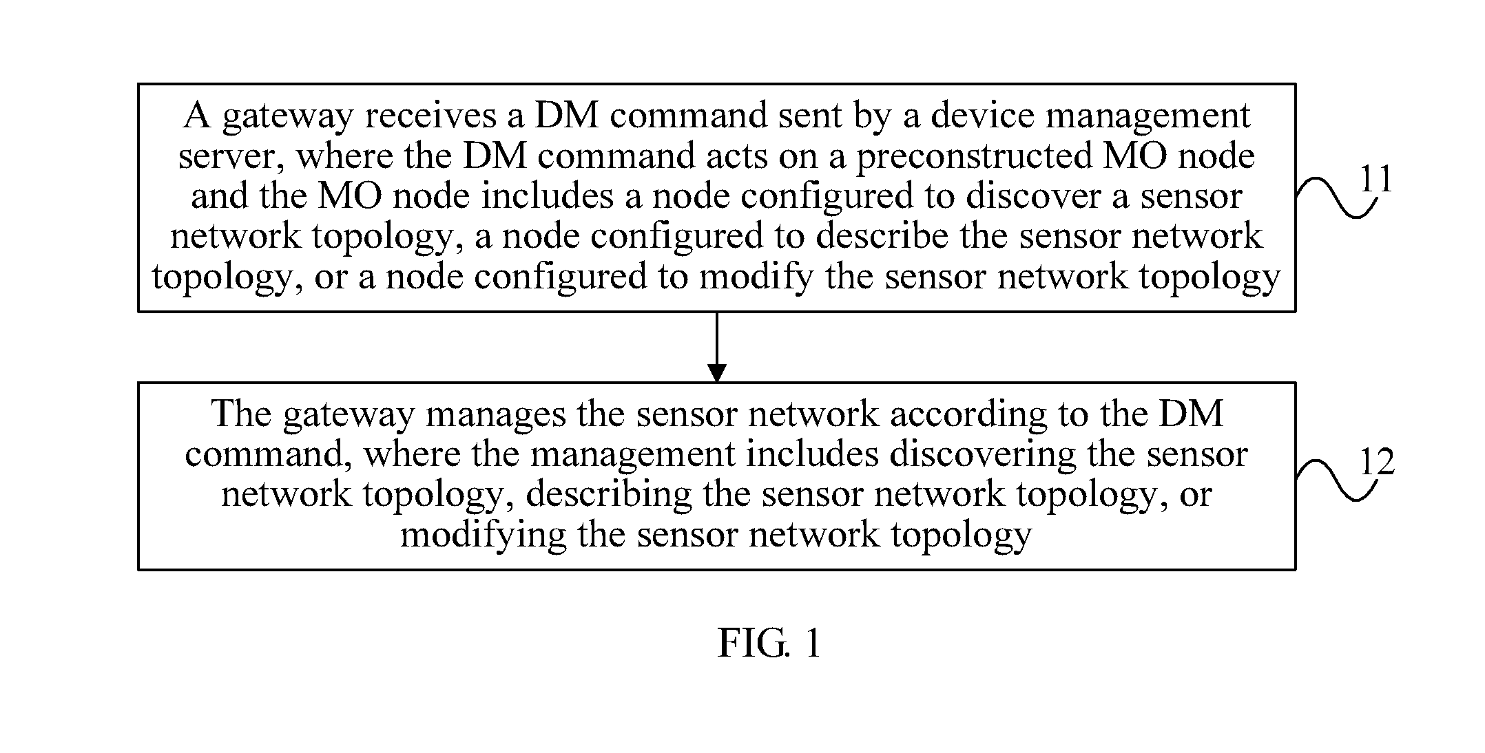
[0029]FIG. 1 is a schematic flow chart of a method of the present invention. The method includes the following steps:

[0030]Step 11: A gateway receives a DM command sent by a device management server, where the DM command acts on a preconstructed MO node and the MO node includes a node configured to discover a sensor network topology, a node configured to describe a sensor network topology, or a node configured to modify a sensor network topology.

[0031]The node configured to describe a sensor network topology includes at least one of:

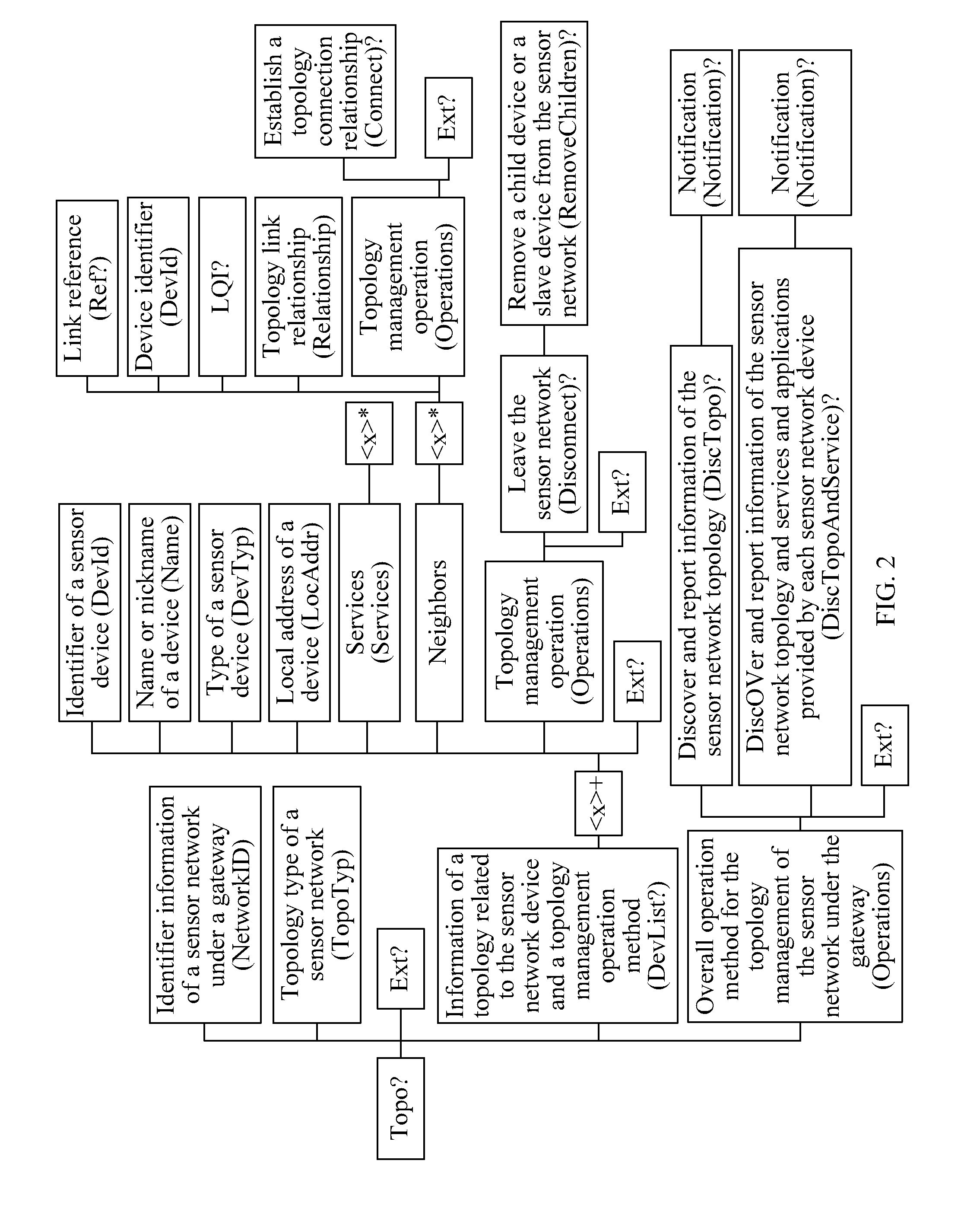
[0032]a first MO node configured to describe overall information of the sensor network, in which, for example, referring to the topology tree shown in FIG. 2, the first MO node includes at least one of: Topo / NetworkId and Topo / TopoTyp;

[0033]a second MO node configured to describe characteristic information of each sensor device and / or information of a topology connection relationship among the sensor devices, in which, for example, referring to the topo...

embodiment 2

[0104]FIG. 5A and FIG. 5B is a schematic flow chart of a method of the present invention. This embodiment describes remote discovery of a ZigBee network topology and device service information through a gateway. Referring to FIG. 5A and FIG. 5B, this embodiment includes the following steps:

[0105]Step 51: A device management server (DM Server) establishes a remote DM session with an M2M gateway (M2M gateway).

[0106]The DM Server may also be an M2M service platform.

[0107]The DM server may establish the remote DM session with the M2M gateway using a standard DM protocol in the prior art. In the management session, the DM server can perform remote device management for the M2M gateway using an existing DM technology.

[0108]Step 52: The DM server sends a DM execution (Exec) command (Exec:Topo / Operations / DiscTopoAndService) to the M2M gateway.

[0109]Specifically, if the DM server expects to further discover information of a sensor network topology connected to the M2M gateway and informatio...

embodiment 3

[0160]FIG. 6 is a schematic flow chart of a method of the present invention. This embodiment describes the step of reporting joining / leaving of a ZigBee network device through a gateway. Referring to FIG. 6, this embodiment includes the following steps:

[0161]Step 61: A device management server (DM Server) establishes a remote DM session with an M2M gateway (M2M gateway).

[0162]For the specific content, refer to step 51.

[0163]Step 62: The DM server sends a DM replacement (Replace) and an execution (Exec) command (Replace:Topo / Operations / DiscTopo / Notification=True; Exec:Topo / Operations / DiscTopo) to the M2M gateway.

[0164]Specifically, if the DM server may obtain a notification of a change of the topology information after the DM server discovers the information of a sensor network topology connected to the M2M gateway the DM server first sends to the M2M gateway one DM replacement (Replace) command, where, the replacement command acts on the management object node Topo / Operations / DiscT...


PUM


Abstract

A method for remotely managing a sensor network topology includes: receiving a device management DM command sent by a device management server, where the DM command acts on a preconstructed management object MO node and the MO node includes a node configured to discover a sensor network topology, a node configured to describe a sensor network topology, or a node configured to modify a sensor network topology; and managing a sensor network according to the DM command, where the management includes discovering the sensor network topology, describing the sensor network topology, or modifying the sensor network topology. By adopting the present invention, remote topology management of a sensor network successive to an M2M gateway can be implemented and the complexity for implementing the management is reduced.

Description

CROSS-REFERENCE TO RELATED APPLICATIONS[0001]This application is a continuation of International Application No. PCT / CN2011 / 074608, filed on May 24, 2011, which claims priority to Chinese Patent Application No. 201010527473.9, filed on Oct. 27, 2010, both of which are hereby incorporated by reference in their entireties.FIELD OF THE INVENTION[0002]The present invention relates to the communications technologies, and in particular, to a method for remotely managing a sensor network topology and a gateway.BACKGROUND OF THE INVENTION[0003]The machine-to-machine communications (Machine-to-Machine Communications, M2M) is a type of networked application and service with machine-to-machine intelligent interactions being the core. The M2M communications implements data communications without human intervention by embedding wireless or wired communication modules and application processing logic in machines, so as to satisfy user's informatization requirements in the aspects such as detectin...

Claims


Application Information

Patent Timeline
IPC IPC(8): H04L12/24H04W4/50H04W4/70
CPCH04L41/08H04W24/02H04W88/16H04W4/50H04W4/70H04W84/18H04L41/12H04L67/12
Inventor ZHANG, YONGJINGBIAN, YONGGANGHUANG, CHENGDING, CHUANSUOJIN, LEIMU, LUNJIAN
Owner HUAWEI CLOUD COMPUTING TECH CO LTD
Learn More