
Ink filling method and inkjet recording apparatus

Inactive Publication Date: 2013-10-31
CANON KK
View PDF4 Cites 11 Cited by
  • Summary
  • Abstract
  • Description
  • Claims
  • Application Information

AI Technical Summary

Benefits of technology

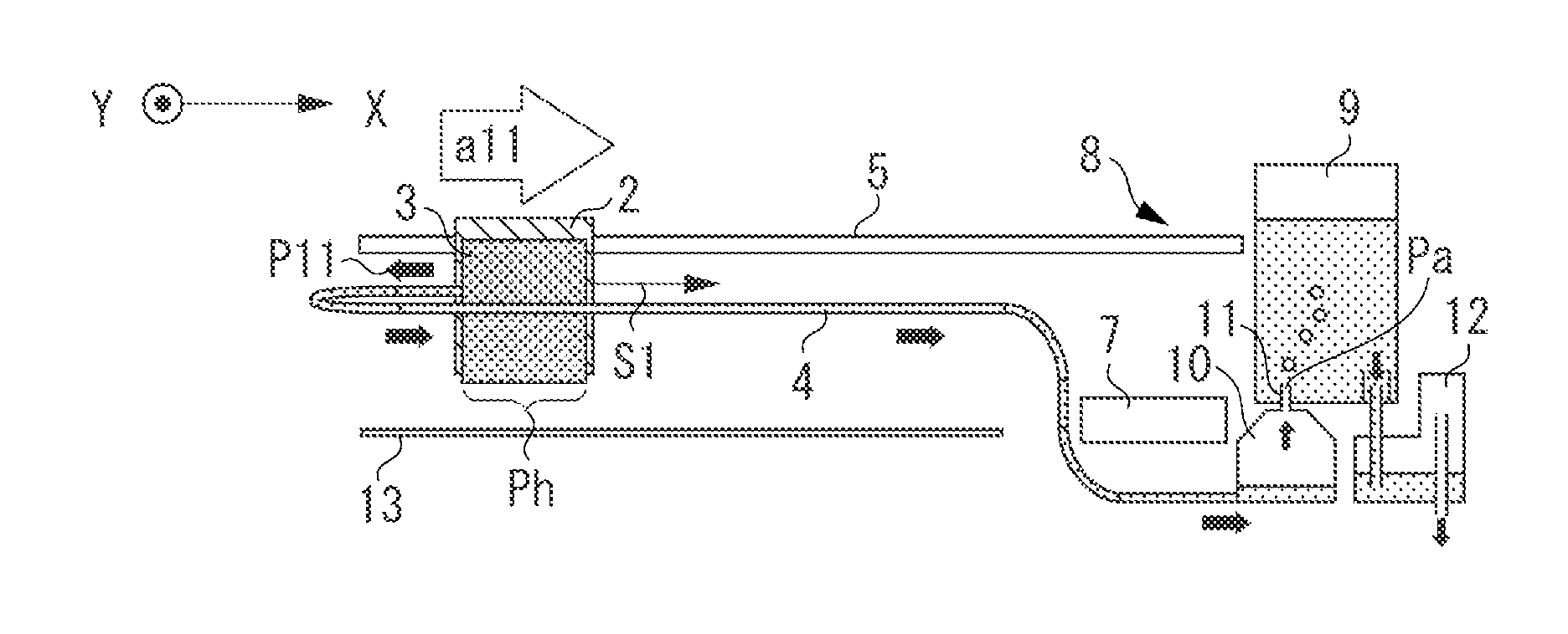
The present invention provides an inkjet recording apparatus that prevents interruptions in recording due to ink supply interruption. This is achieved by controlling acceleration of a carriage and forcibly supplying ink from the main tank to the sub-tank when the empty volume in the sub-tank reaches a certain level. This ensures continued recording efficiency and prevents the waste of time during printing of one image.

Problems solved by technology

When the large inkjet recording apparatus records an image having a high printing duty such as a photographic tone image, a large amount of ink is consumed.
Although the large-volume main tank is used in the large inkjet recording apparatus, a large amount of ink can be consumed depending on the type of recording image or the volume of printing.
The consumption of a large amount of ink causes an increase in frequency of main tank replacement.
This decreases the recording efficiency due to a waste of time for replacing the main tank.
Moreover, if a recording operation is interrupted in the middle of recording on one recording medium for main tank replacement, the lapse of time causes color unevenness between before and after the interruption and deteriorates image quality.
This valve includes a volume-changeable member (hereinafter referred to as a diaphragm valve), and the operation of this diaphragm valve can cause negative pressure in the sub-tank.
Consequently, when the diaphragm valve is operated, ink cannot be supplied to the recording head, and thus the inkjet recording apparatus cannot continue the recording operation.
That is, the ink filling operation to the sub-tank cannot be performed along with the recording operation.
The recording operation is interrupted during the ink filling to the sub-tank since the ink filling operation needs to be performed independently from the recording operation, thereby causing a decrease in the recording efficiency.
However, in a case where there is not much ink in the main tank to fill the sub-tank with ink by the dynamic pressure, ink in the main tank may become empty before the sub-tank is filled with a sufficient amount of ink.
In case of such a situation, an ink shortage may occur during recording of one image, although the recording apparatus has the sub-tank.

Method used


Image

  • Ink filling method and inkjet recording apparatus
  • Ink filling method and inkjet recording apparatus
  • Ink filling method and inkjet recording apparatus

Examples


Embodiment Construction

[0030]Various exemplary embodiments, features, and aspects of the invention will be described in detail below with reference to the drawings.

[0031]An inkjet recording apparatus can be used to perform a recording operation on a recording medium by discharging ink. Particularly, the inkjet recording apparatus can be applied to devices such as a printer, a copying machine, business equipment such as a facsimile apparatus, and industrial production equipment. The use of such an inkjet recording apparatus enables recording to be performed on various recording media made of paper, thread, fiber, cloth, leather, metal, plastic glass, wood, and ceramic.

[0032]The term “recording” used throughout the present specification represents not only a case where a meaningful image such as characters and graphics is provided on a recording medium, but also a case where a meaningless image such as patterns is provided on a recording medium.

[0033]Moreover, the term “ink” should be broadly interpreted. T...


PUM


Abstract

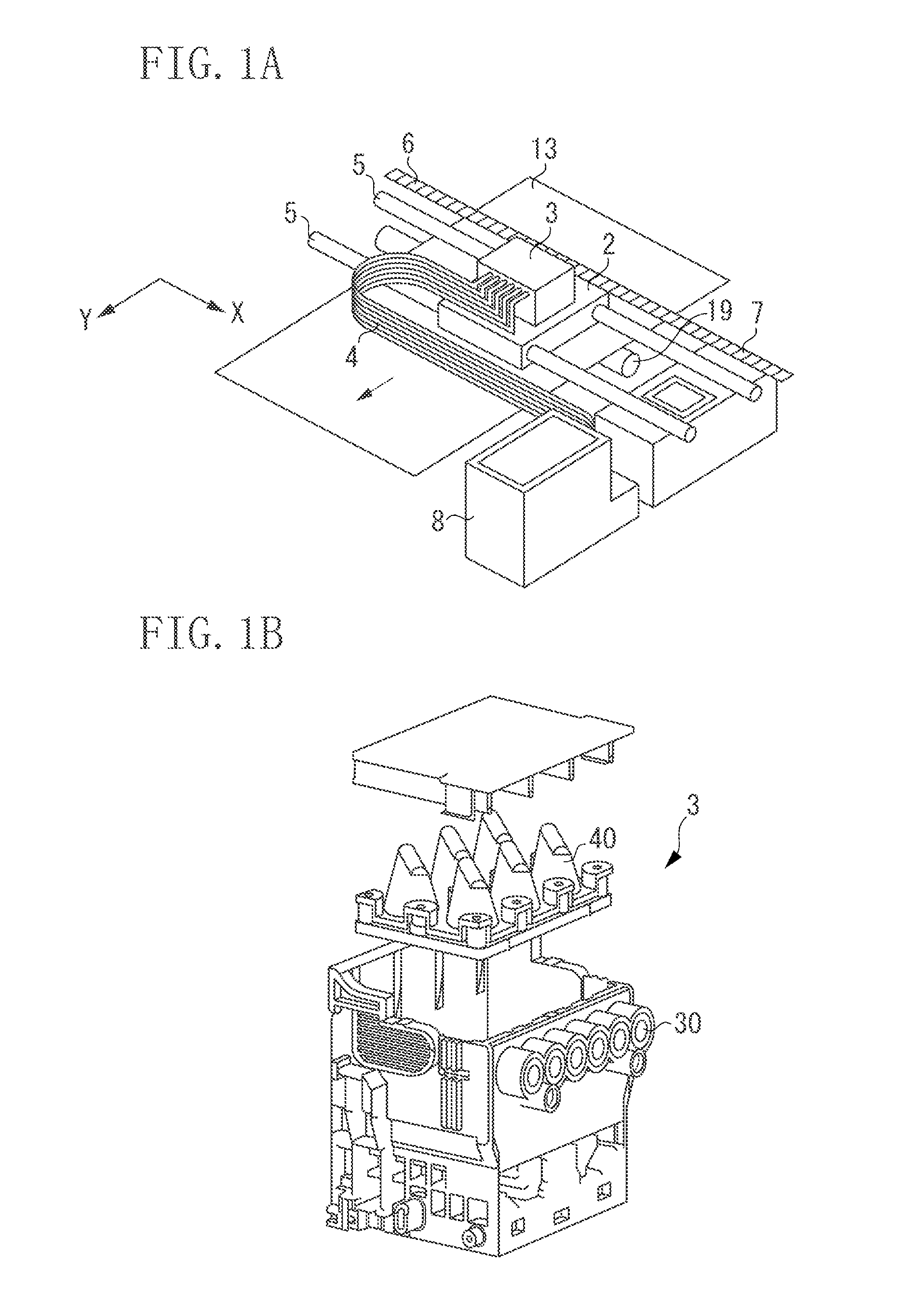
An inkjet recording apparatus includes a recording head, a carriage with the recording head mounted thereon, a main tank, a sub-tank configured to be supplied with ink from the main tank via a tube, a supply tube configured to connect the recording head and the sub-tank, a supply unit connected to the supply tube and configured to supply ink from the main tank to the sub-tank, and a control unit configured to control acceleration of the carriage and to control the supply unit, wherein, when an empty volume in the sub-tank is greater than or equal to an ink volume in the main tank, the supply unit is controlled to supply ink to the sub-tank.

Description

BACKGROUND[0001]1. Field[0002]Aspects of the present invention generally relate to an ink filling method for filling a sub-tank with ink from a main tank disposed in an inkjet recording apparatus, and an inkjet recording apparatus employing the method.[0003]2. Description of the Related Art[0004]Recently, an ink jet recording apparatus has been used to record various types of images on a large recording medium such as A1 size and A0 size. This type of inkjet recording apparatus generally employs a configuration in which an inkjet recording head (hereinafter referred to as a recording head) mounted on a carriage performing reciprocating scanning in a main scanning direction is connected via a tube to a large-volume main tank (hereinafter referred to a main tank) to supply ink to the recording head.[0005]The large inkjet recording apparatus has a wide range of uses including recording of various types of images from monochrome line drawings to photographic tone images. When the large ...

Claims


Application Information

Patent Timeline
IPC IPC(8): B41J2/175
CPCB41J2/17566B41J2/175B41J2/17509B41J2/17523B41J2/17553B41J29/38B41J2002/17579
Inventor UETSUKI, MASAYAYOKOZAWA, TAKUDANZUKA, TOSHIMITSUKATO, MASATAKAIBE, TSUYOSHITOMIDA, ASAKOKOMATSU, HIROAKI
Owner CANON KK
Learn More