
Control of network lighting systems

a network lighting and control technology, applied in the direction of electric variable regulation, process and machine control, instruments, etc., can solve the problems of limiting the efficiency and flexibility of the final system, high bandwidth, etc., and achieve the effect of improving the control of the networked lighting system

Active Publication Date: 2013-10-31
KONINKLIJKE PHILIPS ELECTRONICS NV
View PDF2 Cites 30 Cited by
  • Summary
  • Abstract
  • Description
  • Claims
  • Application Information

AI Technical Summary

Benefits of technology

The invention provides an efficient and flexible way to send the same message to multiple luminaire lights in a networked lighting control system. By using a single multicast message, the system can control each luminaire by compressing the light settings using functions to reduce the communication load. This saves transmission bandwidth and allows for individual control of each lamp, even in a group of lamps. Overall, the invention improves efficiency and flexibility in controlling a network of lamps.

Problems solved by technology

However, all these approaches require transmitting the individual light settings of each luminaire, and thus, they require high bandwidth and limit the efficiency and flexibility of the final system.

Method used


Image

  • Control of network lighting systems
  • Control of network lighting systems
  • Control of network lighting systems

Examples


Embodiment Construction

[0054]In the following, functionally similar or identical elements may have the same reference numerals.

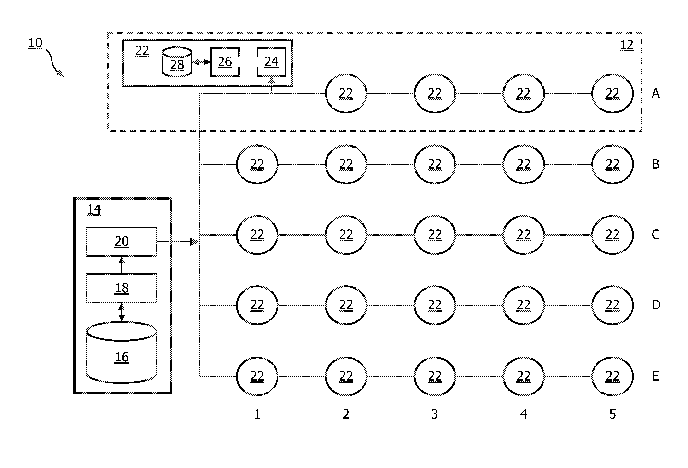
[0055]The term “lighting system” used in the following refers to a networked lighting system, i.e. a lighting system with a network for connecting all luminaries with one or more lighting controllers via a wired and / or wireless network.

[0056]The term “luminary” refers to a light source with a control interface, i.e. an electronic circuitry for controlling a lighting in accordance with a control command received over a network of a networked lighting system particularly from a lighting controller. A luminary may comprise one or even more light sources, for example several LEDs, which are controlled by the same control circuitry. A luminary does not have to contain control circuitry and light source(s) in a one unit, for example in the same housing, instead the control circuitry may be also arranged external and provided to control several light sources for example via a bus interfa...


PUM


Abstract

The invention relates to the control of networked lighting systems, particularly large scale networked lighting systems, and more specifically to an efficient transmission of messages to control luminaries of a networked lighting system. A basic idea of the invention is to provide an efficient and flexible multicast, particularly group cast message that addresses several or a group of luminaires, and that can control the addressed luminaries in an efficient way by compressing the distributed light settings using a function in order to reduce the communicational overhead. An embodiment of the invention relates to a method for controlling a networked lighting system comprising the steps of—selecting several controllable luminaries of the networked lighting system (S10), —combining control information for each one of the selected luminaries to a set of information control information (S12), —selecting at least one predetermined function for compressing the set of control information by associating an input related to a selected controllable luminary to the control information for the selected controllable luminary from the set of control information (S14), —creating a multicast message addressed to the selected luminaries and comprising information regarding the selected predetermined function (S16), and—transmitting the created multicast message (S18).

Description

TECHNICAL FIELD[0001]The invention relates to the control of networked lighting systems, particularly large scale networked lighting systems, and more specifically to an efficient transmission of messages to control luminaries of a networked lighting system.BACKGROUND ART[0002]In the future, networked lighting systems will evolve particularly due to new developments on lighting sources such as LED (Light Emitting Diode) luminaries leading to a higher number of light sources. Networked lighting systems with a high number of light sources or luminaries are also referred to as large scale networked lighting systems.[0003]In conventional networked lighting systems, control is performed by using commands, which are transmitted over the communication medium of the lighting systems to set, for example, the light levels of the luminaires. These commands can be unicasted, addressing one luminaire, to set the light level of this luminaire to a specified value. Alternatively, such commands can...

Claims


Application Information

Patent Timeline
IPC IPC(8): H05B37/02H05B44/00
CPCH05B37/0272H05B47/175H05B47/19H04L12/2803H05B47/105H05B45/00H05B47/18H04L67/12
Inventor GARCIA MORCHON, OSCARDENTENEER, THEODORUS JACOBUS JOHANNES
Owner KONINKLIJKE PHILIPS ELECTRONICS NV
Learn More