
Storage container

Inactive Publication Date: 2013-10-31
FRONTIER LOGISTICS
View PDF6 Cites 96 Cited by
  • Summary
  • Abstract
  • Description
  • Claims
  • Application Information

AI Technical Summary

Benefits of technology

The present invention is a container designed for storing and unloading materials from vehicles. It has sloping walls that make it easier to unload materials using gravity, pneumatic, and optional auger devices. The container also includes enclosed discharge equipment that can be transported and stored separately from the vehicle. The technical effect of this invention is that it eliminates the need for special equipment and makes the process more efficient and easier.

Problems solved by technology

Therefore, many conventional transportation systems are not capable of storing the material independent from the transportation equipment.
This leads to increased costs for both transportation and storage.
However, the bag increases the difficulty of loading and unloading particulate material and requires disposal.
However, the hopper car must be used in connection with a railway cart and does not provide for storage of particulate material without the railway cart.
In addition, this system is not acceptable for job sites not located next to railway tracks.
This results in the material being exposed to the elements which can lead to spoilage, dilution, change in composition through moisture absorption, and / or loss of material.
Another risk is theft of the material.
Each loading and unloading step results in additional labor costs and loss of material.

Method used


Image

  • Storage container
  • Storage container
  • Storage container

Examples


Embodiment Construction

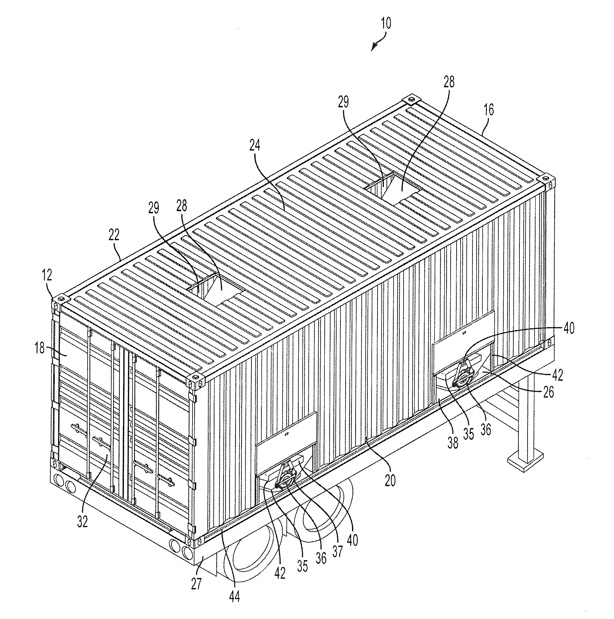
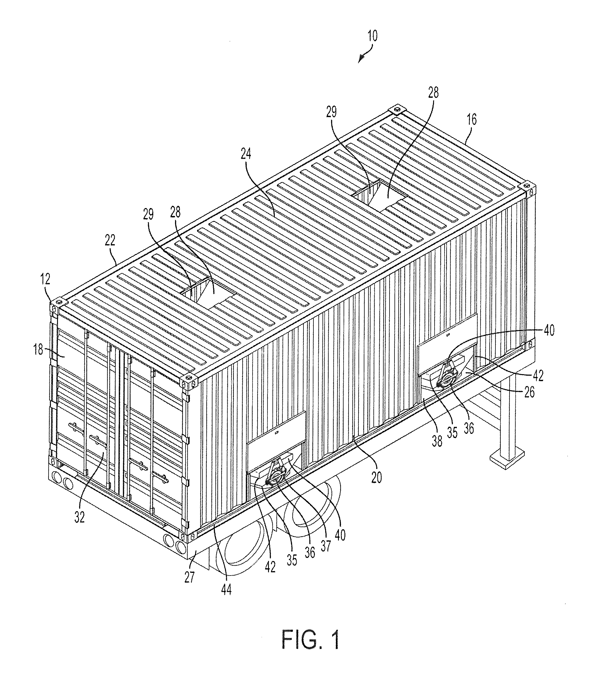
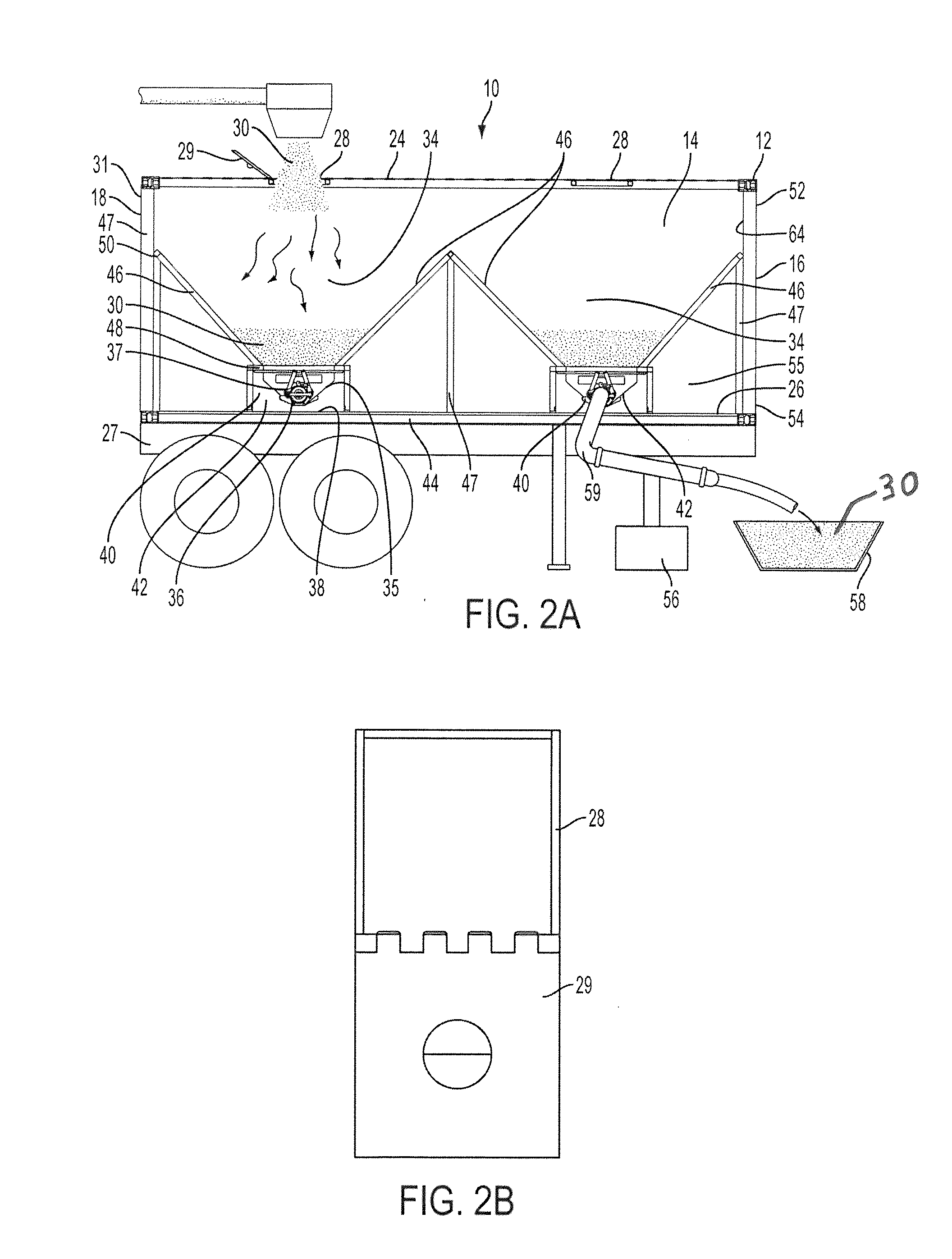
[0022]Referring now to FIGS. 1 and 2, a container is generally designated as 10 and includes a frame 12. A storage cavity 14 is defined by opposing front 16 and back walls 18, opposing side walls 20, 22, a top wall 24, and a floor 26. Each of the front 16 and back 18 walls, side walls 20, 22, top wall 24 and floor 26 connect to the frame 12. The example container 10 generally includes walls 16-24 and floor 26 that are coextensive with the frame 12. Some other embodiments may include one or more walls 6-24 and floor 26 that are not coextensive with the frame 12. The walls 16-24, floor 26, and frame 12 may be constructed as desired, but in many applications a useful balance between strength, weight and durability is desirable. In many applications, the frame is constructed of steel of sufficient gauge, with walls 6-24 and floor 26 likewise constructed of steel. They can be attached to the frame 12 by welding, fasteners or other suitable connection means.

[0023]Although dimensions may b...


PUM


Abstract

A self-contained container for storing and transporting particulate material is provided, the container including a frame, a storage cavity defined by opposing front and back walls, opposing side walls, a top wall, and a floor, each of the front and back walls, side walls, top wall and floor connected to the frame, at least one loading port in the top wall, and at least one discharge region including at least one discharge port and one sloped wall configured for removing material from the container. The discharge region and discharge port being positioned within the frame.

Description

BACKGROUND[0001]Some embodiments of this invention relate to storage containers, with one example being a container for shipping and / or storage of particulate material, for example, granular, powdered and pelleted materials.[0002]Particulate material is often mined, manufactured or refined, then transported by motor vehicle, such as a dump truck, to a job site. Many conventional systems have been designed to transport particulate material, but require a special vehicle or equipment for unloading it. Therefore, many conventional transportation systems are not capable of storing the material independent from the transportation equipment. This leads to increased costs for both transportation and storage.[0003]One conventional system teaches loading a sealed bag in a container and using a titled support frame to discharge the material using gravity. However, the bag increases the difficulty of loading and unloading particulate material and requires disposal. In addition, a specially des...

Claims


Application Information

Patent Timeline
IPC IPC(8): B65D88/00
CPCB65D88/68B65D88/74B65D90/14B65D90/54
Inventor COOK, GEORGEWISEMAN, GLENNNEWKIRK, KEVINLUSK, BURTMADLER, JAMES
Owner FRONTIER LOGISTICS
Learn More