
Air Mover

a technology of air moving and moving parts, which is applied in the direction of lighting and heating apparatus, liquid fuel engines, heating types, etc., can solve the problems of increasing evaporation, affecting building performance, and exposing the building to water and moisture, so as to reduce drying time and increase evaporation.

Inactive Publication Date: 2013-10-24
BEARUP ADAM DEAN +2
View PDF13 Cites 9 Cited by
  • Summary
  • Abstract
  • Description
  • Claims
  • Application Information

AI Technical Summary

Benefits of technology

Enables flexible and efficient power management, accurate moisture content monitoring, and optimized drying operations across diverse remediation sites, enhancing the effectiveness and precision of water damage remediation processes.

Problems solved by technology

The building may also be affected by a natural disaster, such as a flood.
In addition, pipes may burst or leak or fluid drainage systems may backup, thereby exposing the building to water and moisture.
In some situations, heaters may also be used to increase the ambient temperature of the drying air and / or the area being dried, which increases evaporation and decreases drying time.
As one of skill in the art will appreciate, entering a structure to obtain sensor readings is costly and time consuming.
Pedrazza and Armstrong, however, fail to recognize the need for maintaining functionality while providing a constant, flexible, and safe power to drying equipment, which are located in a variety of remediation sites and that require a variety of available power configurations.
The prior art does not disclose any device capable of such intelligent operation.
Further, neither Pedrazza nor Armstrong discloses a penetrating moisture sensor for use in efficiently remediating a variety of wood structures and that has a geometry that allows for effective installation.

Method used


Image

  • Air Mover
  • Air Mover
  • Air Mover

Examples


Embodiment Construction

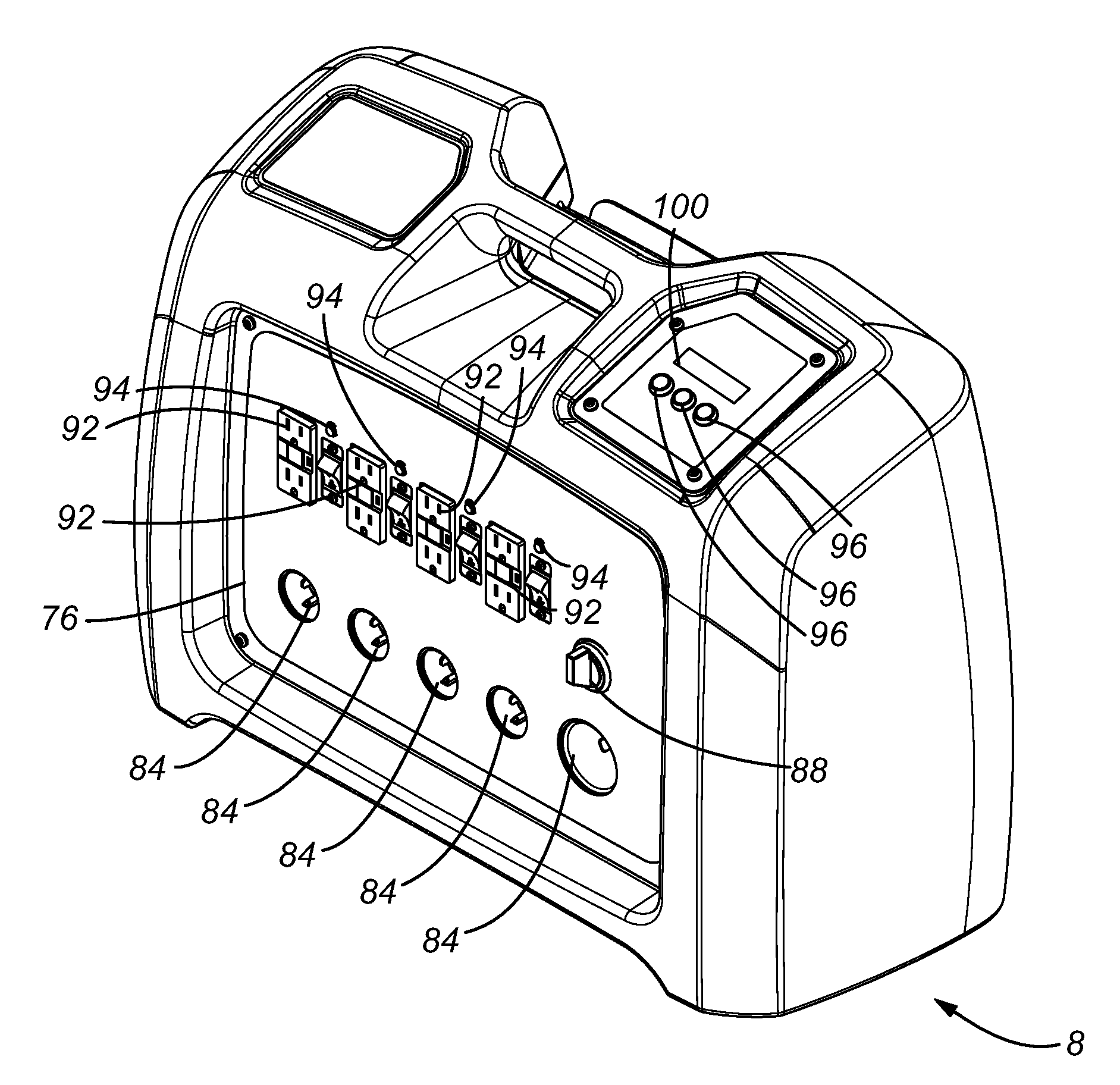
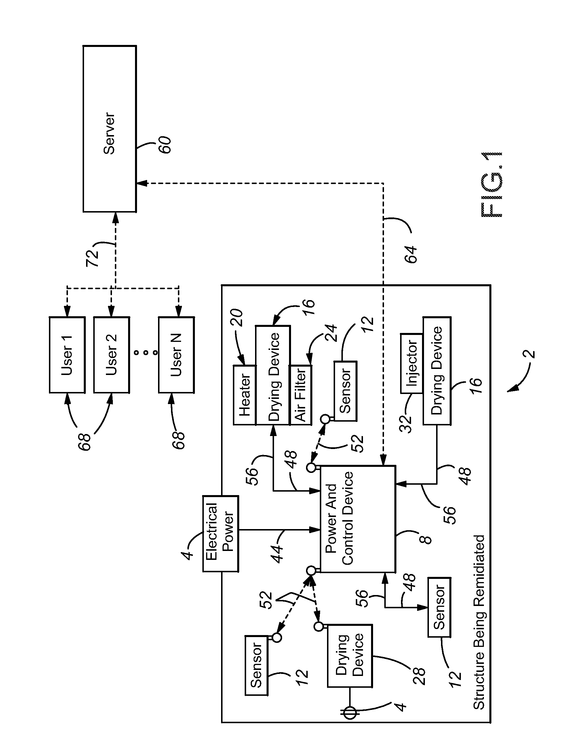
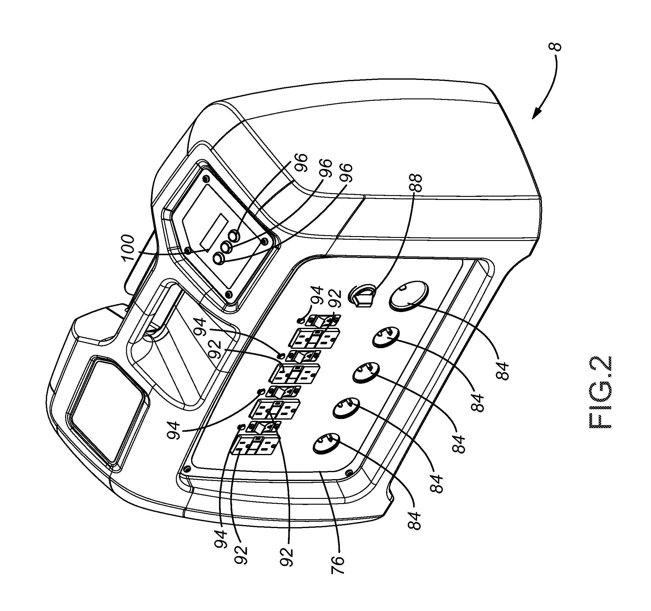
[0086]FIG. 1 depicts a general overview of major components that may be utilized with one embodiment of the contemplated remediation system. As can be seen, a building being remediated 2 typically will include various forms of electrical power 4. A power and control device 8, sensors 12, and several drying devices, which may include an air mover 16 (which may possess an integrated heater 20, air filter 24, or chemical injector 32), and a dehumidifier 28, are located within the structure 2. The drying devices may be connected to their own electrical power 4 and communicate with the power and control device 8.

[0087]Electrical power 4 is provided to the control device 8 through conventional wiring 44 from within the structure, such as 220 volt 30 amp or perhaps multiple of 110 volt 15 amp currents, or from another source, such as a portable gas powered electrical generator. The control device 8 may condition supplied electrical current to provide appropriate current to drying devices, ...


PUM


Abstract

An overall restoration system useful in removing moisture from structures is provided. The contemplated system includes a power and control device, a series of sensors, and a number of various different drying equipment, all capable of communication with a remote server. The system is highly portable, flexible and cost-efficient to manufacture and operate.

Description

[0001]This U.S. Non-Provisional Patent Application is a Continuation of U.S. patent application Ser. No. 12 / 986,727, filed Jan. 7, 2011, which claims priority to U.S. Provisional Patent Application Ser. No. 61 / 293,593, filed Jan. 8, 2010, the entire disclosures of which are incorporated by reference herein.FIELD OF THE INVENTION[0002]Embodiments of the present invention generally relate to the use, including integrated use, of various devices in a system that effectively and efficiently removes moisture and prevents the development of mold from growing in water damaged buildings, structures, etc.BACKGROUND OF THE INVENTION[0003]Systems and devices are commonly used to dry walls, floors, ceilings and other parts of the inside of a building that have been exposed to unusually high amounts of moisture. Moisture may enter one or more rooms of the building through any of several ways. For instance, fire sprinklers may be activated or firefighters may douse the building with water to cont...

Claims


Application Information

Patent Timeline
Patent Type & Authority Applications(United States)
IPC IPC(8): F04D25/08
CPCF04D25/08E04B1/70F24F3/1405
Inventor BEARUP, ADAM DEANEMENHEISER, MATTSHARK, ERIC L.
Owner BEARUP ADAM DEAN
Learn More