
Virtualized Wireless Communication System and Establishing Method thereof

a wireless communication system and wireless communication technology, applied in the field of virtualized wireless communication system, can solve the problems of limiting the accuracy and practicability of evaluation, affecting the accuracy of evaluation, so as to achieve good scalability, low cost, and high flexibility

Inactive Publication Date: 2013-10-17
IBM CORP
View PDF1 Cites 11 Cited by
  • Summary
  • Abstract
  • Description
  • Claims
  • Application Information

AI Technical Summary

Benefits of technology

The present invention provides a solution with flexible, scalable, and low-cost advantages over prior art. Compared to centralized virtualization solutions, it significantly reduces management data overhead and enhances real-time behavior of the entire system.

Problems solved by technology

However, obviously, such method is limited by site, maintenance, hardware cost, and the like.
Thus, only in a small range of cases (with fewer communication nodes and smaller test area) can such evaluation be performed, which limits the accuracy and practicability of the evaluation.
For example, in a real wireless network, interference can exist between several mutually adjacent communication nodes.
As a result, when these nodes attempt to transmit data at the same time, loss of data packets can occur because of the existence of interference.
However, the above solution in the prior art has the following defects.
Thus, the central server becomes a performance bottleneck of the whole virtualized system.
Secondly, in this solution, each data packet must be initially analyzed and judged by the server, which impacts the real-time behavior of communication flows.
Finally, purchasing a high-performance server will require a considerably high cost and expenditure, and the stability of the server also will become a critical factor for the whole virtualized network operation.

Method used


Image

  • Virtualized Wireless Communication System and Establishing Method thereof
  • Virtualized Wireless Communication System and Establishing Method thereof
  • Virtualized Wireless Communication System and Establishing Method thereof

Examples


Embodiment Construction

[0025]Preferred embodiments of the present disclosure will be described in greater detail below with reference to the accompanying drawings. The accompanying drawings have shown those preferred embodiments of the present disclosure, however, it should be understood that, the present disclosure can be implemented in various forms, but are not limited to these embodiments illustrated herein. On the contrary, these embodiments are provided for making the present disclosure more thorough and complete, such that the scope of the present disclosure can be completely delivered to one of ordinary skill in the art.

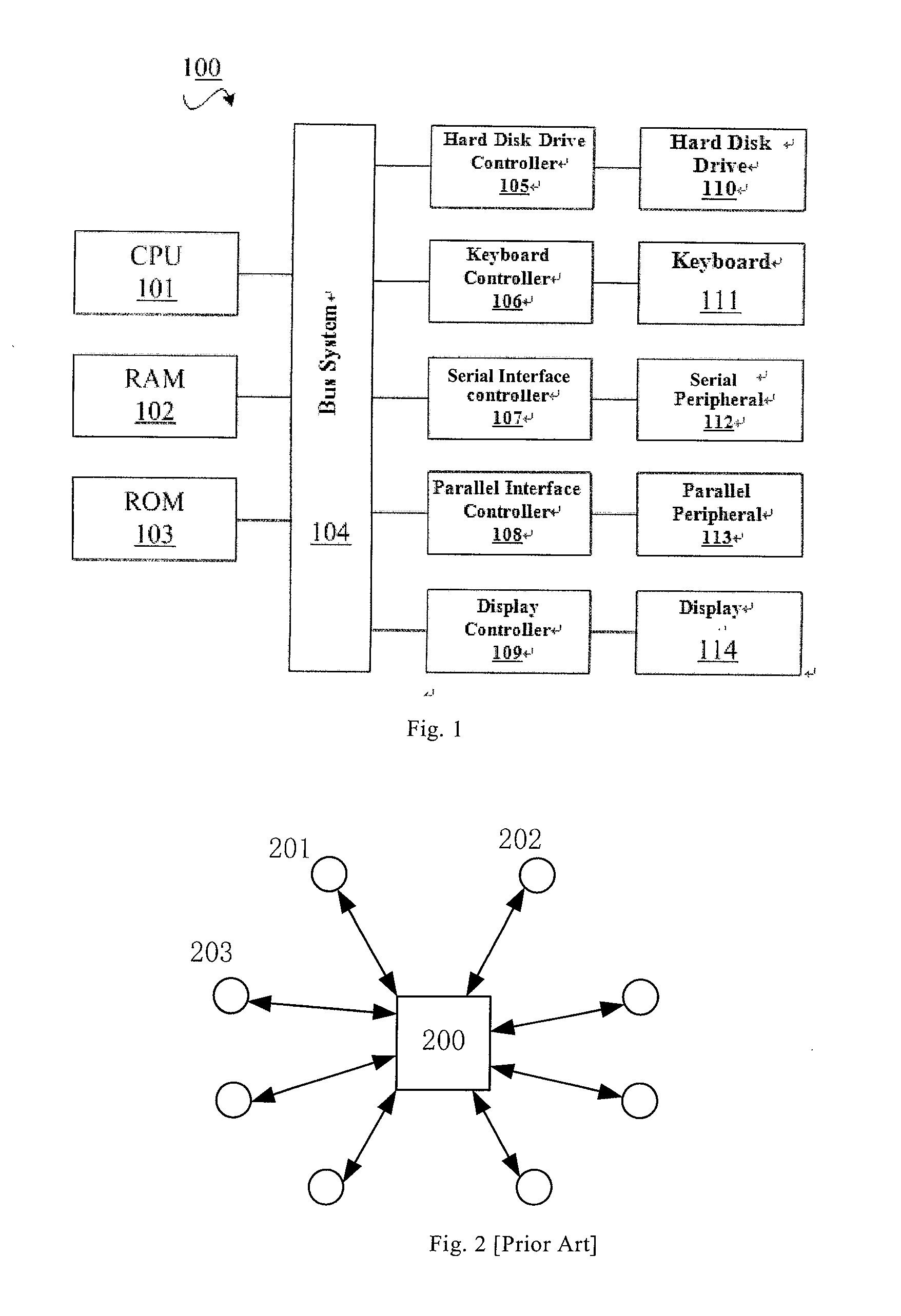
[0026]FIG. 1 shows a block diagram of an exemplary computing system 100 which is applicable to implement the embodiments of the present invention. As shown in FIG. 1, the computing system 100 can include: CPU (Central Processing Unit) 101, RAM (Random Access Memory) 102, ROM (Read Only Memory) 103, system bus 104, hard drive controller 105, keyboard controller 106, serial interface...


PUM


Abstract

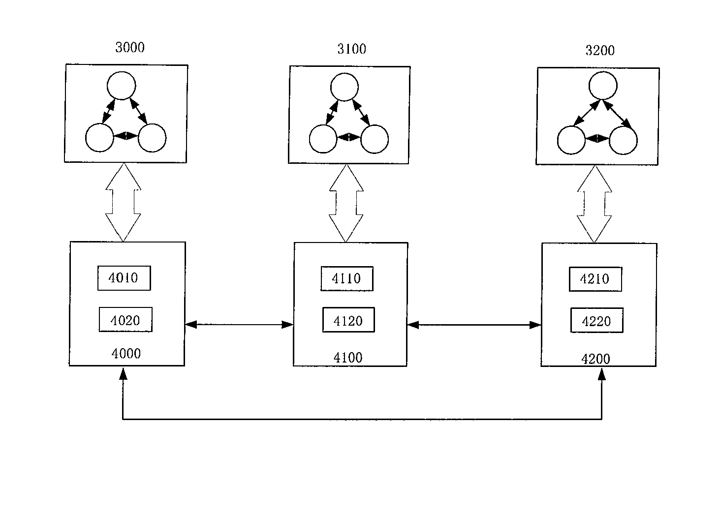
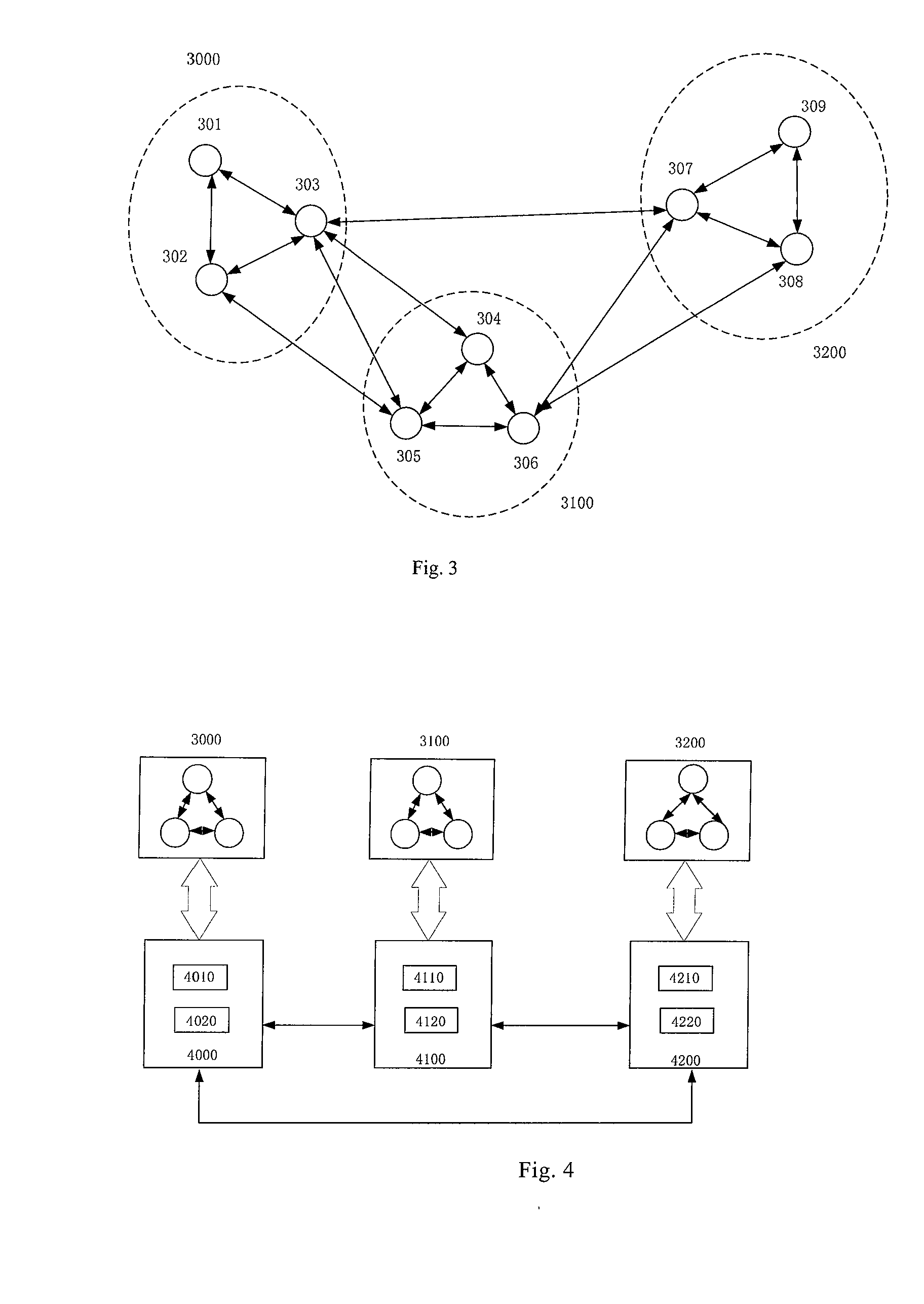
The present application discloses a virtualized wireless communication network and an establishing method thereof. The virtualized wireless communication network system includes a plurality of virtual nodes, the plurality of virtual nodes being divided into multiple virtual node cliques according to interference relations among the plurality of virtual nodes, wherein, each virtual node represents a wireless communication node; and a plurality of clique communication management modules that are one-to-one associated with the multiple virtual node cliques, wherein, each clique communication management module is configured to manage data exchange between an associated virtual node clique and other virtual node cliques, so as to emulate communication behavior of the wireless communication node. The present invention has many advantages such as high flexibility, good scalability, low cost and the like. Compared with a centralized virtualization solution, this solution can significantly reduce management data overhead and thus enhance the real-time behavior of the whole system.

Description

CROSS-REFERENCE TO RELATED APPLICATION[0001]This application claims priority under 35 U.S.C. §119 from Chinese Patent Application No. 20120092334.7 filed Mar. 31, 2012, the entire contents of which are incorporated herein by reference.BACKGROUND OF THE INVENTION[0002]1. Field of the Invention[0003]The present invention relates to a virtualized wireless communication system and an establishing method thereof.[0004]2. Description of Related Art[0005]With the advancement of wireless communication technologies, the development of various wireless communication protocols and wireless communication technologies has attracted more and more attention. As for a new wireless communication technology, it is necessary to evaluate its operation performance prior to practical application.[0006]Generally speaking, there are two existing methods for evaluating a wireless communication technology. One is to set up a real communication system (e.g. including a plurality of nodes, servers, or the like...

Claims


Application Information

Patent Timeline
Patent Type & Authority Applications(United States)
IPC IPC(8): H04W24/06
CPCH04W24/06H04W16/22H04L12/4641
Inventor LI, LILIU, LIANGQU, JUNMEIYUAN, YU
Owner IBM CORP
Learn More