
System and methods for warm white LED light source

a led light source and white light technology, applied in the field of light, can solve the problems of reducing the lumen efficiency, and insufficient light source performance of conventional led-based light sources, so as to reduce the lumen efficiency, reduce the brightness, and improve the cri

Active Publication Date: 2013-10-17
LEDENGIN
View PDF5 Cites 42 Cited by
  • Summary
  • Abstract
  • Description
  • Claims
  • Application Information

AI Technical Summary

Benefits of technology

The patent text explains the process of selecting the optimal numbers and driving currents for different color light sources in order to achieve the desired output color. This can be difficult in both the multiple emitter and multiple-chip single emitter approaches, as it requires adjusting the current in the emitters or chips. This adjustment can lead to increased complexity and cost of the product. The patent proposes a solution to simplify the process and reduce costs.

Problems solved by technology

As described above, conventional LED-based light sources are inadequate in meeting the requirements for bright warm white light.
The conventional LED lamp with mixed off-white emitters and red emitters suffer from many limitations.
These limitations include, for example, (1) a diffuser is needed for mixing red and the off-white emitters, which reduces the lumen efficiency; and (2) collimation of the lamp light is difficult because the off-white and red emitters are located over a large area in the light source.
As a result, the conventional LED warm white lamps tend to have good CRI, but have low brightness and are not suited for narrow beam applications.
The conventional warm white LED emitter having a mixture of yellow and red phosphors pumped by blue LED chips suffer from low efficiency in part because the currently available red phosphor, which needs to be thermally stable, has low lumen efficiency, for example, 30 lm / W, or so.
To achieve higher CRI using shorter wavelength blue requires red the phosphor with longer wavelength, resulting in even lower luminous efficiency.
Further, the manufacturing yield tends to be low with disposing yellow and red phosphors on blue LED chips in a partially assembled LED emitter.
The variations in the emitters and phosphors make it difficult to achieve the desired light color.
Adjusting the current require additional circuitry, increasing the complexity and cost of the product.

Method used


Image

  • System and methods for warm white LED light source
  • System and methods for warm white LED light source
  • System and methods for warm white LED light source

Examples


Embodiment Construction

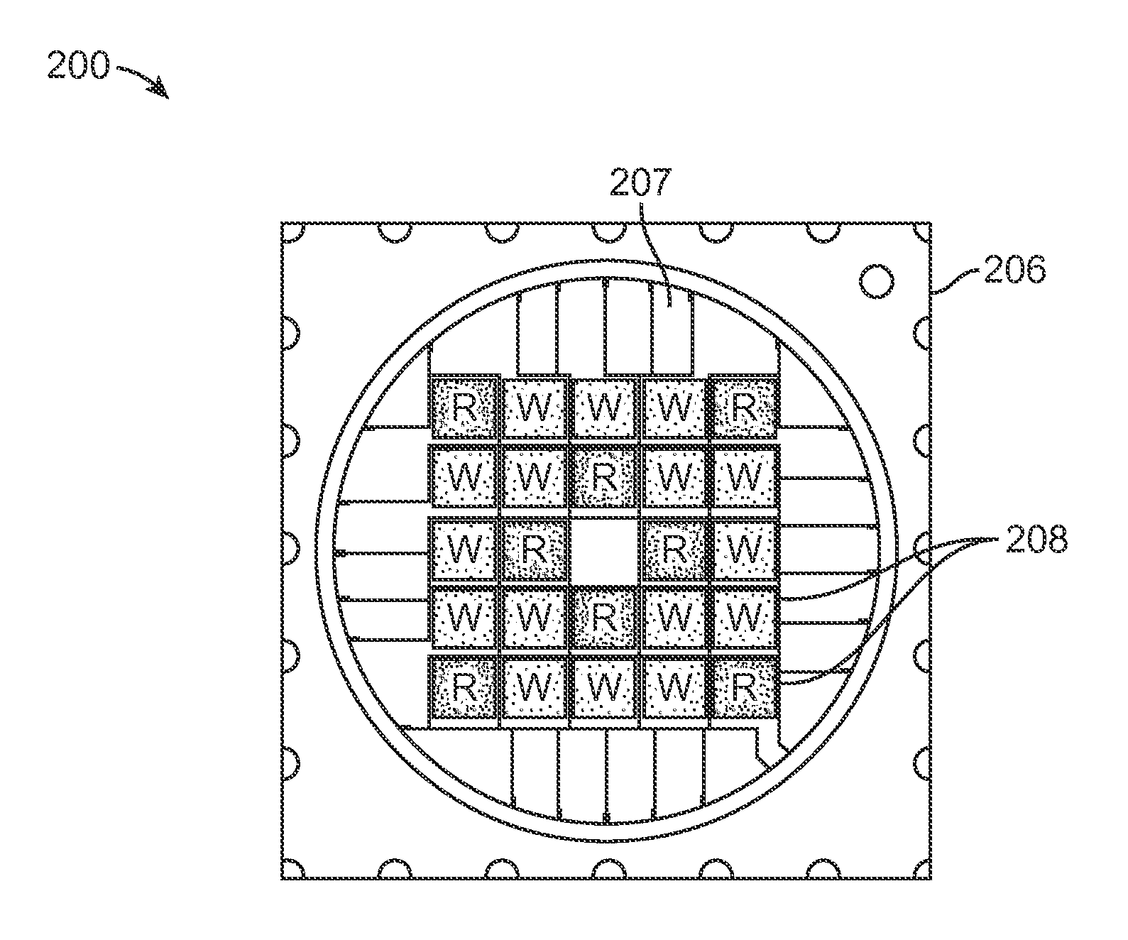
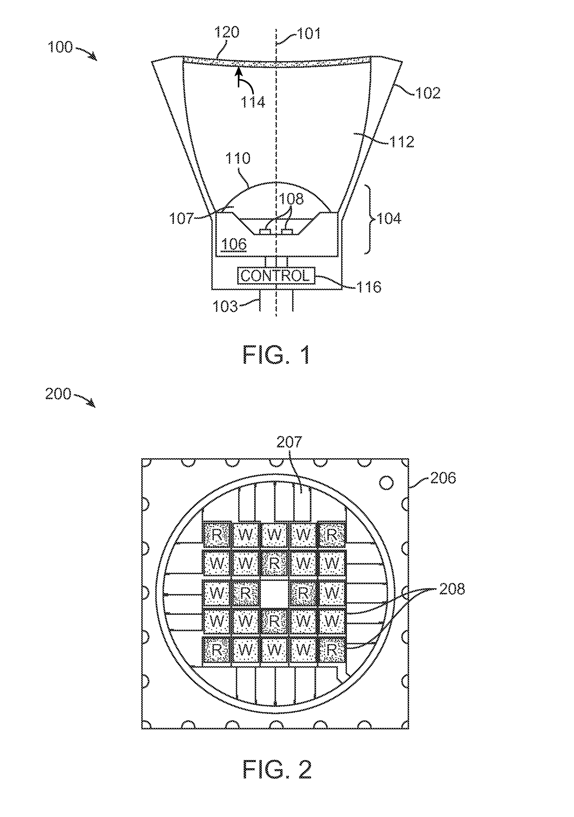
[0019]Embodiments of the present invention provide a single emitter structure with mixed LED dice which generate greenish and red light, rather than mixing emitters, combined with a color mixing total internal reflection lens. Embodiments of the invention also provide methods for forming emitters with high lumen efficiency warm white. Embodiments of this invention have been applied to form 9-die, 12-die, and 24-die emitters of warm white with high lumen efficiency, high CRI and R9. Other emitter configurations can also be formed using methods for forming LED dice for use in a single emitter for generating desired light color and brightness according to embodiments of the invention also include.

[0020]FIG. 1 is a simplified cross-sectional side view of an LED-based lamp 100 according to an embodiment of the present invention. Lamp 100, which is cylindrically symmetric about an axis 101, has a housing 102, which can be made of aluminum, other metals, plastic, and / or other suitable mate...


PUM


Abstract

An LED light emitter includes a single emitter structure having a substrate with a plurality of light emitting diodes (LEDs) arranged thereon, wherein the plurality of LEDs includes at least one first LED die that produces a first color light, and at least one second LED die that produces a second color light. The LED light emitter also includes a total internal reflection (TIR) lens positioned to collect light emitted from the single emitter structure and adapted to mix the light from the plurality of LEDs to produce a uniform light. The plurality of LEDs are selected such that the light output by the LED light emitter has a desired color temperature when an equal current is supplied to all of the plurality of LEDs.

Description

CROSS-REFERENCES TO RELATED APPLICATIONS[0001]This application claims priority to U.S. Provisional Patent Application No. 61 / 624,054, filed Apr. 13, 2012, commonly owned and incorporated herein by reference in its entirety. This application is also related to U.S. patent application Ser. No. 13 / 338,912, filed Dec. 28, 2011 (Attorney Docket No. 91924-001600US-808563) and U.S. patent application Ser. No. 13 / 338,936, filed Dec. 28, 2011 (Attorney Docket No. 1924-001700US-808564), commonly owned and disclosures from both of which are incorporated herein by reference in their entirety.BACKGROUND OF THE INVENTION[0002]The present disclosure relates generally to lighting devises and methods for manufacturing and in particular to an LED-based light source for emitting bright warm light.[0003]As light-emitting diode (LED)-based lighting sources become popular, more customers are demanding higher CRI warm white light sources with CRI greater than 80, 90, or even higher. A conventional lamp fi...

Claims


Application Information

Patent Timeline
Patent Type & Authority Applications(United States)
IPC IPC(8): H01L33/58H01L27/15
CPCH01L33/58H01L33/501F21V5/004F21V5/04F21V7/0091H01L2224/48091H01L2224/48463H01L2924/0002F21Y2115/10F21Y2113/17H01L25/0753H01L2924/00014H01L2924/00
Inventor MEI, ZEQUNYAN, XIANTAOJIANG, WU
Owner LEDENGIN
Learn More