
Solenoid activated vacuum control device

a vacuum control device and solenoid technology, applied in the direction of suction devices, intravenous devices, other medical devices, etc., can solve the problems of resistance affecting the functional efficacy of a suction collection system, reducing the flow rate, and preventing the maximum flow potential from being achieved

Inactive Publication Date: 2013-10-10
CASO RICHARD BRAND +3
View PDF3 Cites 40 Cited by
  • Summary
  • Abstract
  • Description
  • Claims
  • Application Information

AI Technical Summary

Benefits of technology

The present invention relates to the field of suction regulators or vacuum flow control devices, which are used in hospitals and clinics to control the removal of fluids and air from patients. These devices have been in use for several decades and are still dependent on mechanical control. The invention aims to provide a solution to mitigate tissue damage caused by the lack of accurate control of the vacuum source. The technical effect of the invention is to provide a vacuum regulator that can accurately control the vacuum pressure to prevent tissue damage and promote safe and effective suctioning procedures.

Problems solved by technology

Resistance causes reduction in flow rates and prevents maximum flow potential from being achieved.
A few manufacturers have made compact, lightweight regulators enclosed in a protective plastic housing; however, some of these devices, are still dependent on the “mechanical” calibration and parts to generate the vacuum pulse.
Too much resistance may compromise the functional efficacy of a suction collection system to the point where potentially life-threatening situations in a clinical setting could occur.
This “fixed mode” does not balance the flow and vacuum requirements.
For example, too many holes will provide adequate flow, but the pressure differential “vacuum” may not be maintained; too few holes will maintain adequate vacuum but may not allow sufficient fluid flow.
Not having accurate control of the vacuum source can pull tissue into the hole leading to injury and or damage to the tissue.
Bleeding, perforation, and death of tissue may ensue along with serious clinical harm.
This leads to a rather inaccurate timing cycle, and one that either cannot be adjusted by the clinician, or if adjusted, is subject to large variation of timing as it tends to drift over time.
Similar problems can also be found in a modular approach that uses a sandwich of plastic plates, air channels, springs and gaskets to achieve the same function as the bellows.

Method used


Image

  • Solenoid activated vacuum control device
  • Solenoid activated vacuum control device
  • Solenoid activated vacuum control device

Examples


Embodiment Construction

[0037]The present invention depicts an inventive solution to the fore mentioned issues related to suction regulators.

[0038]Unless otherwise defined, all terms of art, notations and other scientific terms or terminology used herein are intended to have the meanings commonly understood by those of skill in the art to which this invention pertains. In some cases, terms with commonly understood meanings are defined herein for clarity and / or for ready reference, and the inclusion of such definitions herein should not necessarily be construed to represent a substantial difference over what is generally understood in the art. Many of the techniques and procedures described, or referenced herein, are well understood and commonly employed using conventional methodology by those skilled in the art.

[0039]The indefinite articles “a” and “an,” as used herein in the specification and in the claims, unless clearly indicated to the contrary, should be understood to mean “at least one.”

[0040]The phr...


PUM


Abstract

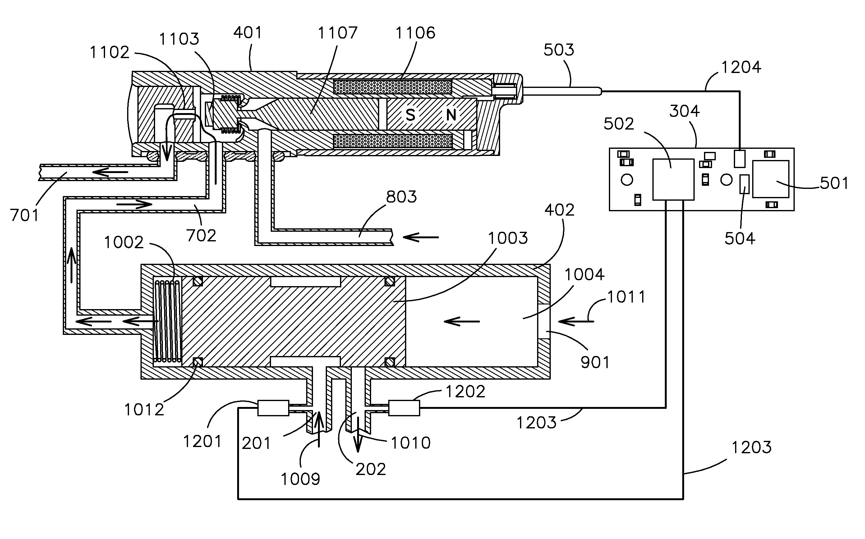
The invention herein applies generally to General-purpose, Surgical and Tracheal suction regulators. In one embodiment of the invention, at least one micro-latching valve is opened and closed by at least one solenoid electromechanical actuator. The micro-latching solenoid valve in turns opens and closes at least one main valve that is connected the hospital vacuum or gas intake conduit. The latching nature of the solenoid, along with its low power activation allows for a battery powered, long-life device. Timing and control of the electromechanical actuator is performed by a low power micro-controller. This provides opportunity for highly accurate timing cycles, user adjustable timing intervals and feedback loop control operations. The invention also features a wireless suction control system of many suction regulators comprising a network. Wherein the plurality of wireless suction regulators are linked to at least one router with at least one wireless transmitter, and the network is linked through the router to the internet.

Description

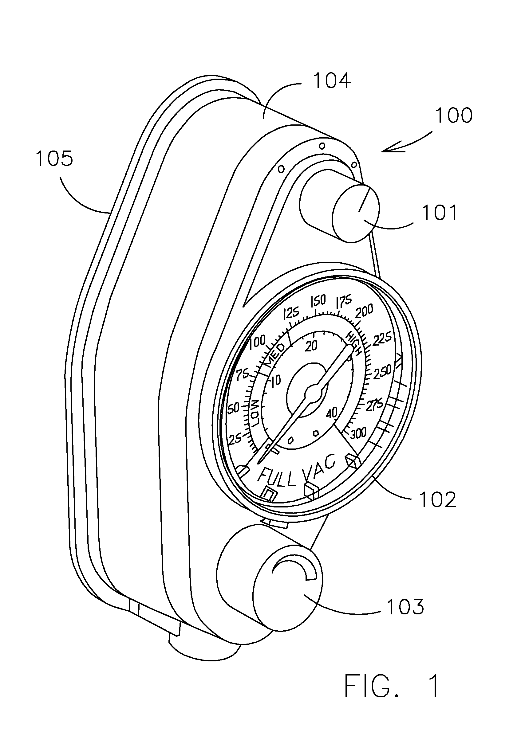
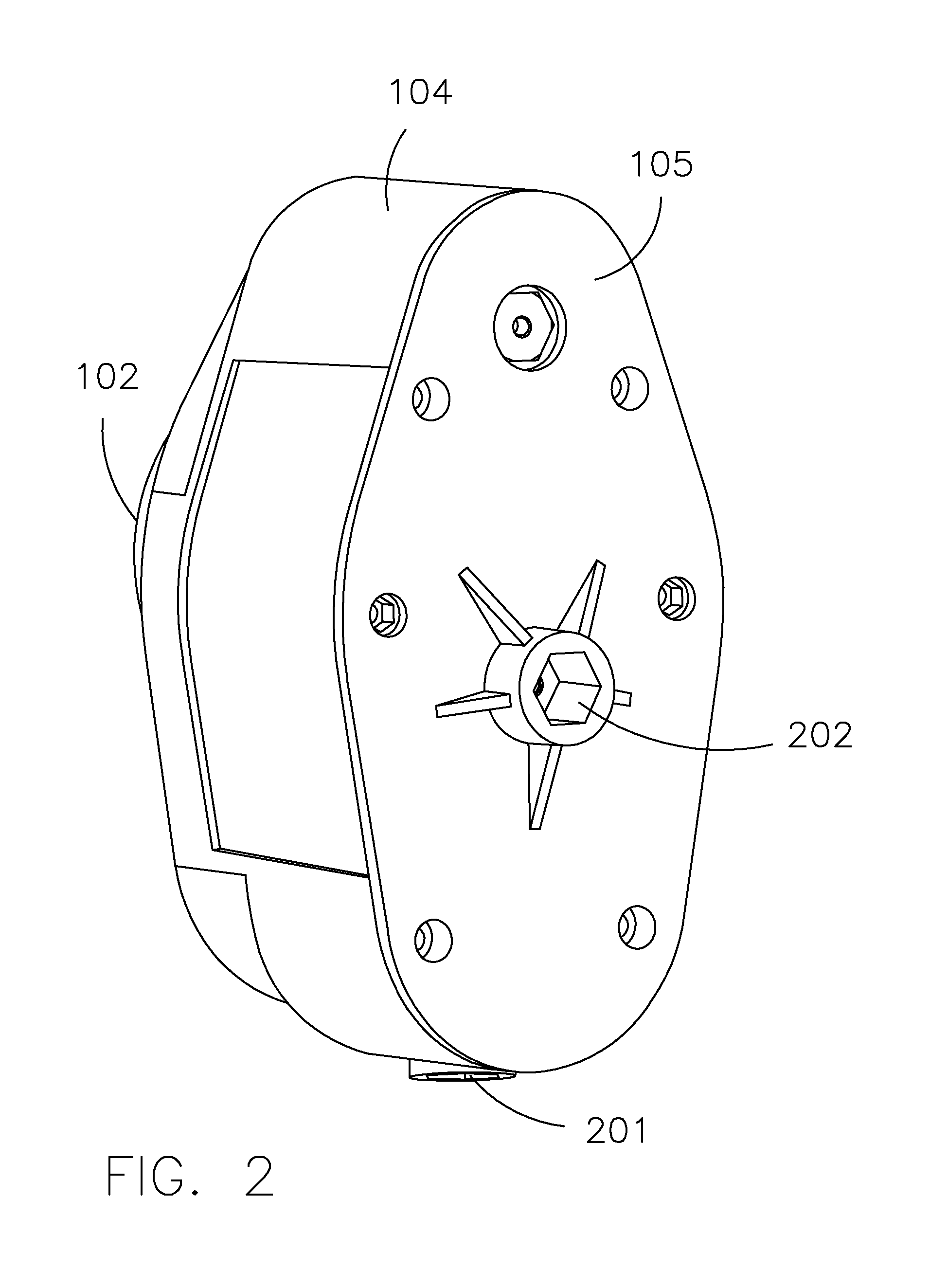
FIELD OF THE INVENTION[0001]The present invention relates to the art of suction regulators or vacuum flow control devices.STATEMENT REGARDING FEDERALLY-SPONSORED RESEARCH AND DEVELOPMENT[0002]Not applicable.BACKGROUND OF THE INVENTION[0003]Suction regulators have been used in hospitals since the 1950s. Dedicated devices or modern regulators designed for specific applications were introduced in the 1960s. The intermittent vacuum regulator was introduced in the 1970s and the combined regulator followed. No significant technological changes have happened since.[0004]Accordingly, hospital and clinic facilities-management systems include vacuum pumps that maintain a negative pressure of −760 millimeters mercury (−1 atmosphere; −14.7 pounds per square inch negative pressure) below atmospheric. Vacuum is defined as the difference between atmospheric pressure and subatmospheric pressure, created by a vacuum-producing device such as a vacuum pump. Suction is defined as the flow of air or flu...

Claims


Application Information

Patent Timeline
IPC IPC(8): A61M1/00
CPCA61M1/0031A61M1/0027A61M2205/3576A61M2205/3561A61M1/732A61M1/74
Inventor CASO, RICHARD BRANDSELEVAN, JAMESBONIN, PETERQUAM, IRVING
Owner CASO RICHARD BRAND
Learn More