
Image forming apparatus

a technology of forming apparatus and forming parts, applied in the direction of electrographic process apparatus, instruments, optics, etc., can solve the problems of toner scattering, parts or components are damaged, toner scattering, etc., and achieve the effect of preventing damage to each par

Inactive Publication Date: 2013-10-10
RICOH KK
View PDF5 Cites 10 Cited by
  • Summary
  • Abstract
  • Description
  • Claims
  • Application Information

AI Technical Summary

Benefits of technology

The present invention is an image forming apparatus that can prevent damage and scattering of developer. It includes a developer container, an image forming unit, and an openable upper cover. The apparatus also has a coupling device to secure the connection between the developer container and the image forming unit when the upper cover is closed. The disconnection preventer prevents the developer container from disconnecting from the retention cover when the upper cover is opened. This invention helps to improve the image quality and prevent contamination during the printing process.

Problems solved by technology

However, because the process cartridge and the toner cartridge are separately formed and therefore are positioned separately, a problem of scattering of toner occurs.
In such a case, when the external cover is closed without the joint portion being appropriately sealed, there occurs a problem that parts or components are damaged or that the toner scatters.

Method used


Image

  • Image forming apparatus
  • Image forming apparatus
  • Image forming apparatus

Examples


Embodiment Construction

[0027]Hereinafter, preferred embodiments of the present invention will now be described with reference to the accompanying drawings.

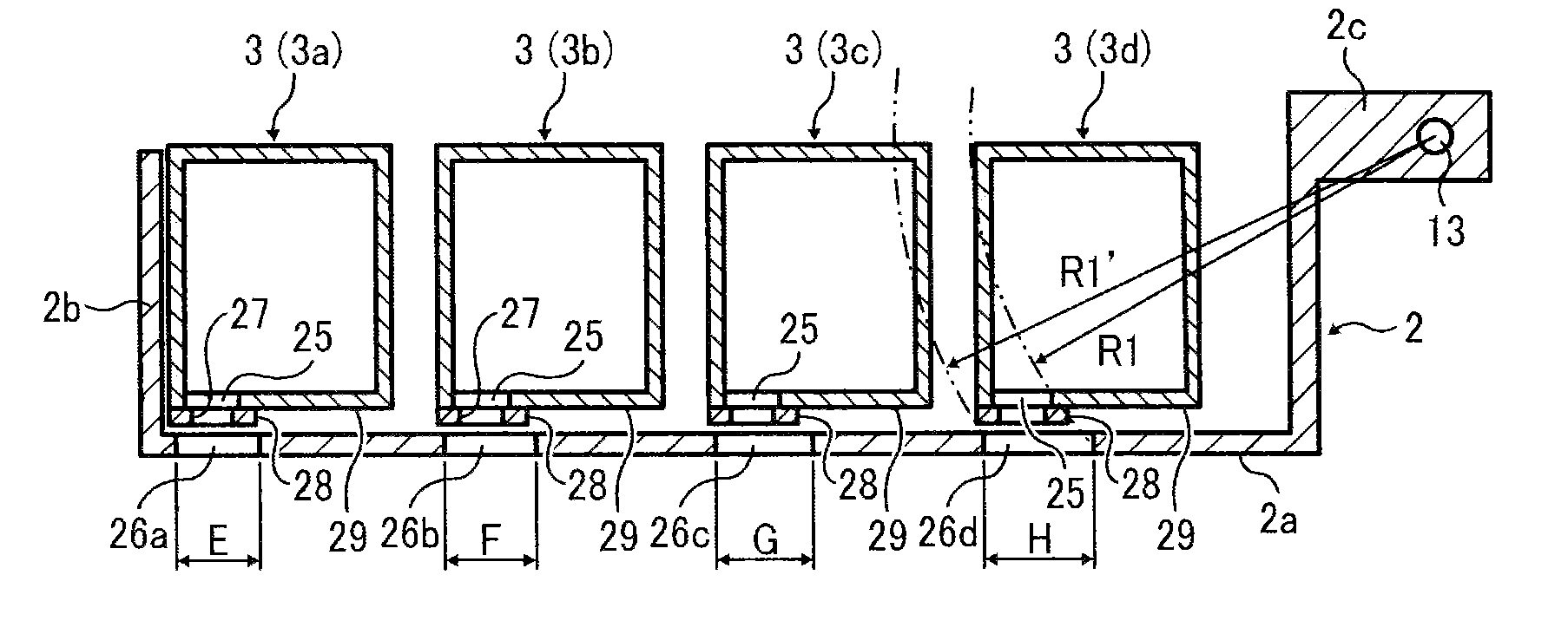
[0028]FIG. 1 is an overview of a color image forming apparatus according to an embodiment of the present invention. FIG. 13 is an overview of a color image forming apparatus 100 according to an embodiment of the present invention and FIG. 14 shows a cross-sectional view of an image forming unit as illustrated in FIG. 13. The image forming apparatus 100 includes four developer containers or toner cartridges 3 (3a, 3b, 3c, and 3d), each including toner of a different color, and image forming units or process cartridges 4 (4a, 4b, 4c, and 4d). The image forming units each include a photoreceptor drum as an image carrier and a developing device, and serve as a developer receiving cartridge.

[0029]The image forming units 4a, 4b, 4c, and 4d are disposed at predetermined intervals in the center of the main body 11 of the image forming apparatus 100. Hereinafter...


PUM


Abstract

An image forming apparatus includes: a developer container to contain a developer therein and a developer supply port; an image forming unit to form an image with the developer from the developer container and including a developer intake port; an openable / closable upper cover configured to cover an upper part of the developer container in a closed state and take out the developer container in an open state; an openable / closable retention cover to hold the developer container and configured to allow the image forming unit to be removed when the retention cover is opened; a coupling device to secure a coupled state of the developer supply port of the developer container with the developer intake port of the image forming unit when the upper cover is in a closed state; and a disconnection preventer to prevent the developer container from disconnecting from the retention cover when the upper cover is opened.

Description

CROSS-REFERENCE TO RELATED APPLICATIONS[0001]The present application claims priority pursuant to 35 U.S.C. §119 from Japanese patent application numbers 2012-089501 and 2012-276900, filed on Apr. 10, 2012 and Dec. 19, 2012, respectively, the entire disclosures of which are incorporated by reference herein.BACKGROUND[0002]1. Technical Field[0003]The present invention relates to an image forming apparatus employing an electrophotographic method, such as a copier, a printer, a facsimile machine, and a multifunction apparatus having one or more capabilities of the above devices.[0004]2. Related Art[0005]In an image forming apparatus employing an electrophotographic method, such as a copier, a printer, a facsimile machine, and a multifunction apparatus having one or more capabilities of the above devices, an electrostatic latent image formed on a photoreceptor or a photoreceptor drum as an image carrier is supplied with toner by a developing means to render the latent image visible and t...

Claims


Application Information

Patent Timeline
Patent Type & Authority Applications(United States)
IPC IPC(8): G03G21/16
CPCG03G21/1647G03G21/1676G03G21/1633
Inventor HASHIMOTO, HARUOFUKUSHIMA, TATSUOTAKAHIRA, MASAFUMI
Owner RICOH KK
Learn More