
Computer-guided system for orienting a prosthetic acetabular cup in the acetabulum during total hip replacement surgery

a technology of acetabular cup and computer guided surgery, which is applied in the field of computer guided surgery, can solve the problems of increasing the cost of the procedure, difficulty in interoperative detection, and difficulty in physically accessing one or more pelvic anatomical landmarks

Inactive Publication Date: 2013-10-03
THORNBERRY ROBERT L
View PDF61 Cites 43 Cited by
  • Summary
  • Abstract
  • Description
  • Claims
  • Application Information

AI Technical Summary

Benefits of technology

The present invention is a computer-guided system that helps position a prosthetic acetabular cup during hip replacement surgery. This system can eliminate the need for a pre-operative CT scan and physical access to pelvic anatomical landmarks during the procedure.

Problems solved by technology

However, this approach relies heavily on the anatomical view available to, and appreciated by, the surgeon, and errors in cup orientation (i.e., tilt) may not be discovered until after the surgery has been completed, since such errors in cup orientation can be difficult to detect interoperatively, even where X-ray imaging is available.
However, in practice, one or more of the pelvic anatomical landmarks can be difficult to physically access during the procedure.
These requirements can add to the cost of the procedure, can lengthen the time required for the procedure, and can be inconvenient for the surgeon (e.g., such as where the surgeon must work around optical trackers protruding into the surgical field).
In this respect it should be appreciated that optical trackers, while providing good spatial resolution, suffer from the disadvantage that they must remain directly visible at all times; electromagnetic trackers, while not requiring direct visual access, suffer from the disadvantage of poor spatial resolution.

Method used


Image

  • Computer-guided system for orienting a prosthetic acetabular cup in the acetabulum during total hip replacement surgery
  • Computer-guided system for orienting a prosthetic acetabular cup in the acetabulum during total hip replacement surgery
  • Computer-guided system for orienting a prosthetic acetabular cup in the acetabulum during total hip replacement surgery

Examples


Embodiment Construction

[0060]Computer-Guided System Using Inertial Measurement Units (IMUs) On The Surgical Table, Pelvis Of The Patient And The Insert For Orienting A Prosthetic Acetabular Cup In The Acetabulum During Total Hip Replacement Surgery

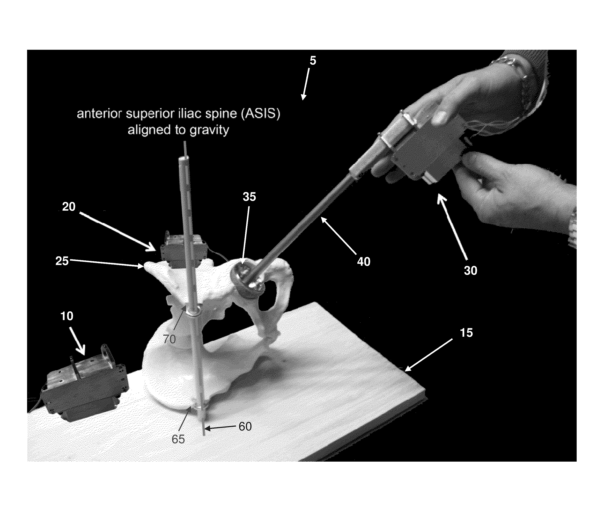
[0061]In one form of the invention, and looking now at FIGS. 3-5, there is provided a computer-guided system 5 for orienting a prosthetic acetabular cup in the acetabulum during total hip replacement surgery. Computer-guided system 5 generally comprises a table inertial measurement unit (IMU) 10 mounted to a surgical table 15 for measuring movement of the surgical table, wherein the surgical table is capable of movement about three axes (X, Y and Z); a pelvic IMU 20 attached to the pelvis 25 of a patient for measuring movement of the pelvis; and an insert IMU 30 attached to an insert 35 which is to be mounted to the pelvis with a desired positioning, with the insert IMU 30 configured for measuring movement of the insert. By way of example but not limitation, tab...


PUM


Abstract

A computer-guided system for orienting an insert during a surgical procedure, the computer-guided system comprising:a surgical table for supporting a patient, the surgical table being capable of movement about three axes;a table inertial measurement unit for measuring movement of the surgical table;a patient inertial measurement unit for measuring movement of the patient;an insert inertial measurement unit for measuring movement of the insert; andcomputational means for determining the relative positioning of the patient and the insert based upon movement of the surgical table, movement of the patient, and movement of the insert.

Description

REFERENCE TO PENDING PRIOR PATENT APPLICATION[0001]This patent application claims benefit of pending prior U.S. Provisional Patent Application Ser. No. 61 / 616,939, filed Mar. 28, 2012 by Robert L. Thornberry for COMPUTER-GUIDED SYSTEM FOR ORIENTING THE ACETABULAR CUP IN THE PELVIS DURING TOTAL HIP REPLACEMENT SURGERY (Attorney's Docket No. THORNBERRY-6 PROV), which patent application is hereby incorporated herein by reference.FIELD OF THE INVENTION[0002]This invention relates to computer-guided surgery in general, and more particularly to computer-guided surgery for orienting the acetabular cup in the acetabulum during total hip replacement surgery.BACKGROUND OF THE INVENTION[0003]Joint replacement surgery seeks to replace portions of a joint with prosthetic components so as to provide long-lasting joint function and pain-free mobility for the patient.[0004]One joint which is commonly replaced, in whole or in part, is the hip joint. The hip joint is located at the junction of the fe...

Claims


Application Information

Patent Timeline
IPC IPC(8): A61F2/46
CPCA61F2/4609A61B19/50A61B2019/5263A61B2019/5248A61B19/5244A61B34/10A61B34/20A61B2034/2048A61B2034/2063
Inventor THORNBERRY, ROBERT L.
Owner THORNBERRY ROBERT L
Learn More