
Lighting unit, display, and three-dimensional display

a three-dimensional display and light source technology, applied in the field of light source, can solve the problems of unfit cost reduction, all display luminance issues, consumption of power and reliability of circuit boards, and the dark display luminance, etc., to achieve high luminance, low power consumption, and high reliability of circuit boards

Active Publication Date: 2013-10-03
SONY CORP
View PDF13 Cites 26 Cited by
  • Summary
  • Abstract
  • Description
  • Claims
  • Application Information

AI Technical Summary

Benefits of technology

The invention provides a lighting unit, display, and three-dimensional display that have high luminance, low power consumption, and high reliability of the circuit board. This is achieved by scanning the light emitted from the display using a light modulation layer and a scanning system instead of traditional scanning methods. This new technology allows for efficient and effective lighting in scan systems while reducing power consumption and improving reliability.

Problems solved by technology

Incidentally, the backlight in such a scan system has an issue of display luminance being dark.
In addition, it is not preferable that a large power be applied to a light source in such an extremely short time in terms of light use efficiency and low power consumption.
Further, reliability of the circuit board is necessarily secured in consideration of inrush power (specifically, large power temporality flows through the light source upon power supply), and thus it is unfit for cost reduction.
However, issues occur in all of display luminance, consumed power, and reliability of a circuit board even by using the methods described in these literatures.

Method used


Image

  • Lighting unit, display, and three-dimensional display
  • Lighting unit, display, and three-dimensional display
  • Lighting unit, display, and three-dimensional display

Examples


first embodiment (fig.1 to fig.15)

1. First embodiment (FIG. 1 to FIG. 15)

[0046]An example in which a horizontal alignment inversion PDLC is provided in a backlight

second embodiment (fig.16 to fig.18)

2. Second embodiment (FIG. 16 to FIG. 18)

[0047]An example in which a vertical alignment inversion PDLC is provided in a backlight

3. Modifications (FIG. 19 to FIG. 27)

[0048]4. Application examples (FIG. 28 to FIG. 30)

[0049]An example in which a backlight is used as a light source of a display

first embodiment

1. First Embodiment

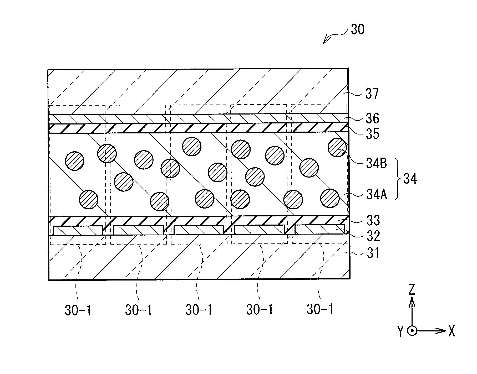
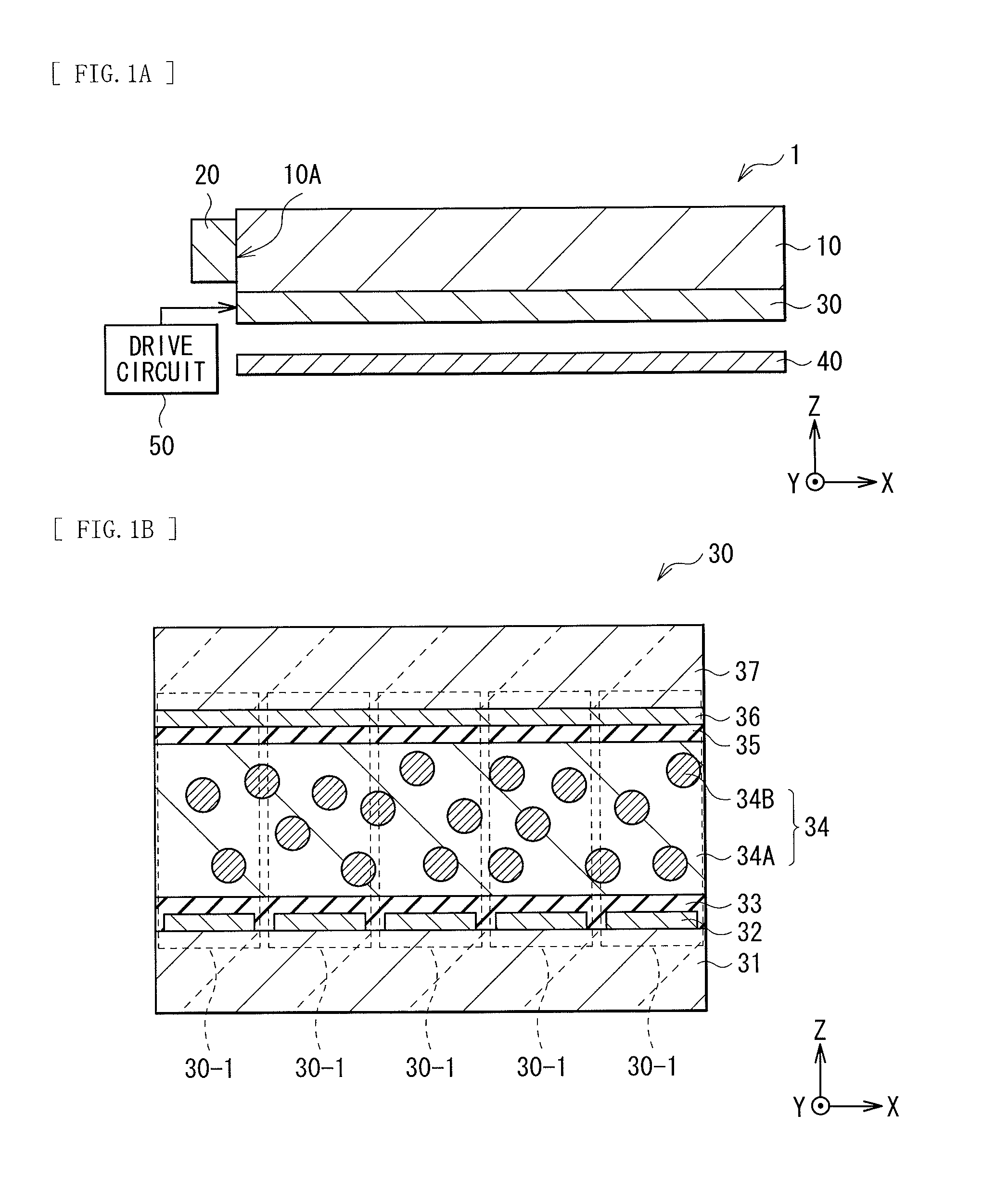
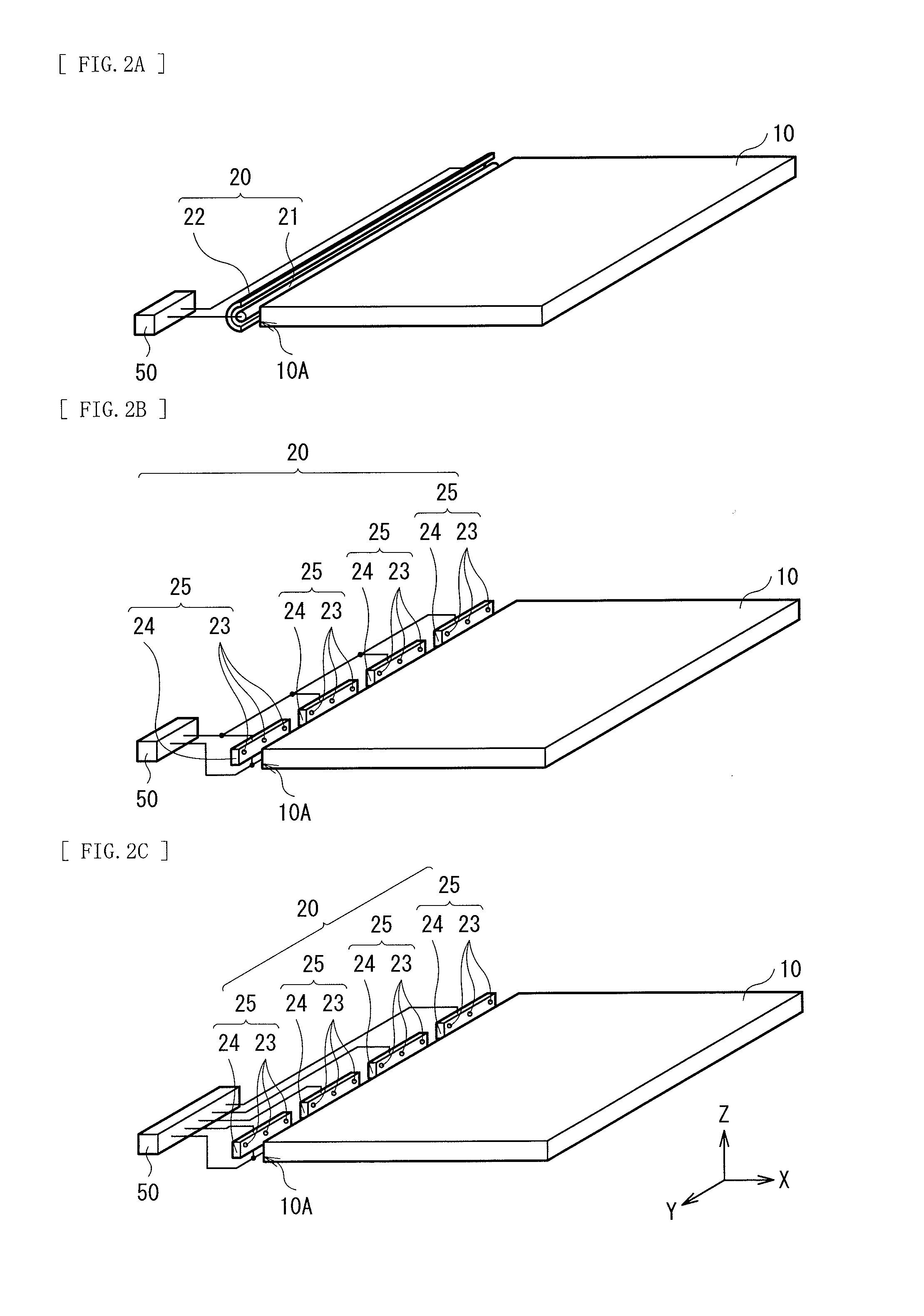
[0050]FIG. 1(A) is a sectional diagram illustrating an example of a schematic configuration of a backlight 1 according to a first embodiment of the invention. The backlight 1 corresponds to a specific example of a lighting unit of the invention. FIG. 1(B) is a sectional diagram illustrating an example of a schematic configuration of a light modulation device in the backlight 1 of FIG. 1(A). Note that FIGS. 1(A) and 1(B) are schematic illustration, and the illustration may not be the same as actual dimensions and shapes. The backlight 1 emits illumination light from an upper surface thereof, and for example, is used for illuminating a liquid crystal display panel and the like from behind. The backlight 1 includes, for example, a light guide plate 10, a light source 20 disposed on a side surface of the light guide plate 10, a light modulation device 30 and a reflector 40 disposed on a back of the light guide plate 10, and a drive circuit 50 driving the light source ...


PUM

PropertyMeasurementUnit
Diameteraaaaaaaaaa
Densityaaaaaaaaaa
Electric potential / voltageaaaaaaaaaa

Abstract

In a scan system, a lighting unit, a display, and a three-dimensional display that have all of high luminance, low power consumption, and high reliability of a circuit board are provided. A light modulation device bonded to a light guide plate is provided with a light modulation layer exhibiting scattering property or transparency to light propagating through the light guide plate. The light modulation layer is interposed between a lower electrode that is configured of a plurality of partial electrodes extending in a direction parallel to a light incident surface and a sheet-like upper electrode. A drive circuit sequentially drives the plurality of partial electrodes to scan a region exhibiting the scattering property of the light modulation layer in a direction orthogonal to the light incident surface.

Description

TECHNICAL FIELD[0001]The invention relates to a lighting unit provided with a light modulation device that exhibits scattering property or transparency to light. Moreover, the invention relates to a display and a three-dimensional display that include the above-described lighting unit.BACKGROUND ART[0002]In recent years, a backlight of a scan system is used to improve moving picture responsiveness of a liquid crystal television. Further, recently, the scan system attracts attention to suppress crosstalk of 3D display using a shutter eyeglasses system. Moreover, particularly in a large television, a combination of an edge light and a light guide plate is a main stream to meet request of thickness reduction, and a backlight capable of being scan driven in a light guide plate system is desired (see PTLs 1 and 2).CITATION LISTPatent Literature[0003]PTL 1: Japanese Unexamined Patent Application Publication No. H1-082019[0004]PTL2: U.S. Patent Application Publication No. 2005 / 00075616 spe...

Claims


Application Information

Patent Timeline
IPC IPC(8): F21V8/00F21V9/40
CPCG02B6/0055G02F1/1334G02B6/0083G02B6/0011H04N13/0438H04N13/0497G02F1/133615G09G3/003G09G3/342G09G3/36G02F2001/133601G02F2202/022G02F2202/40G02F2203/62G09G2310/024G09G2320/0209G02B6/0058H04N13/341H04N13/398G02F1/133601G02F1/13342G02F1/13345G02F1/13347
Inventor OKUYAMA, KENTAROSHINODA, MAKOTONAGATANI, SHINPEITAKAHASHI, YUJISUZUKI, TOMOAKISHINKAI, SHOGOEBISUI, AKIRANISHIMURA, TAIZO
Owner SONY CORP
Learn More