
Increasing dynamic range for x-ray image sensor

a dynamic range and image sensor technology, applied in the field of x-ray image sensors, can solve the problems of inability to increase the intensity of x-rays, limited dynamic range of x-ray sensors, and several unsuccessful attempts to address these shortcomings

Active Publication Date: 2013-10-03
SOH MYUNG JIN +1
View PDF5 Cites 8 Cited by
  • Summary
  • Abstract
  • Description
  • Claims
  • Application Information

AI Technical Summary

Benefits of technology

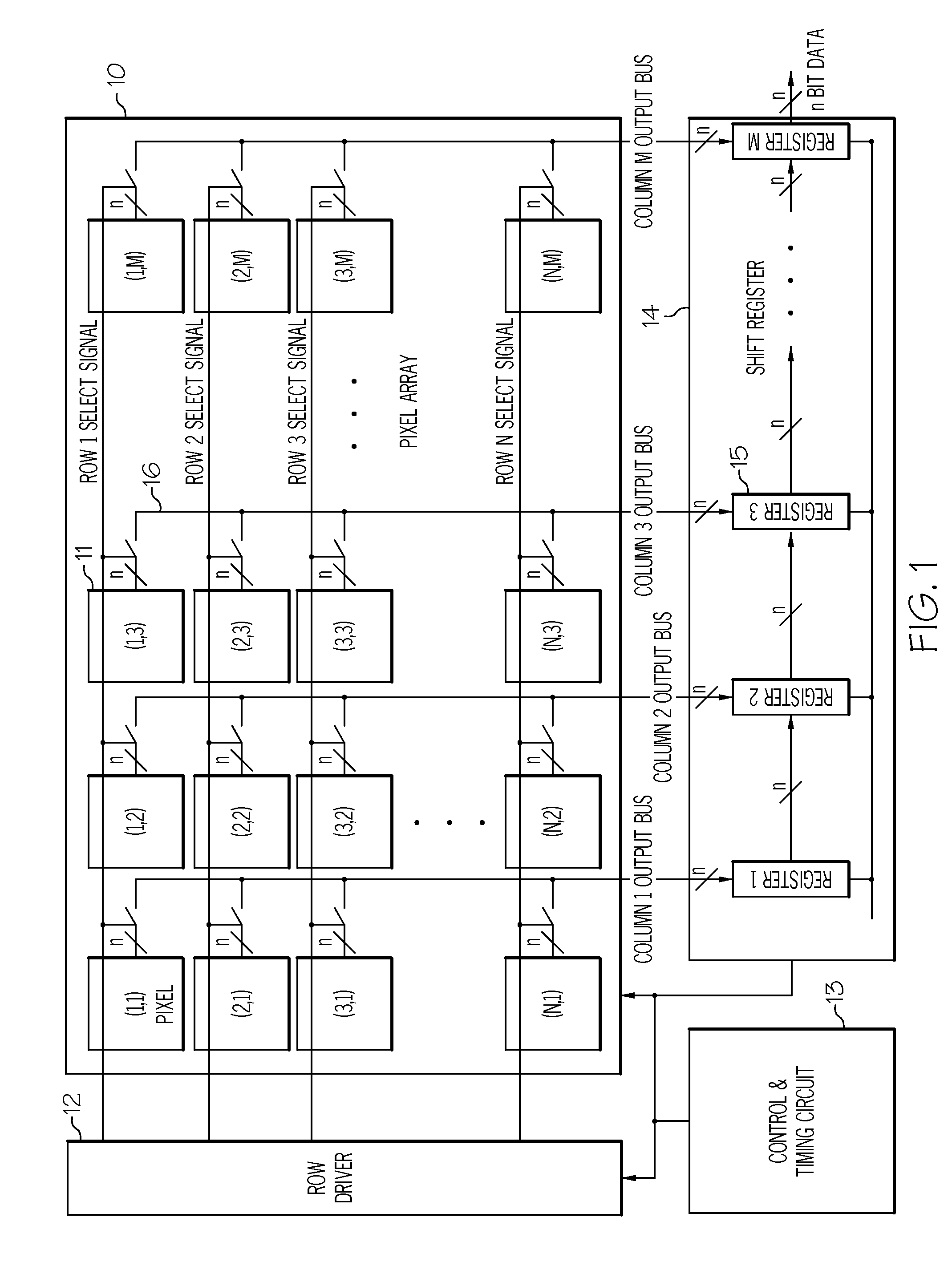
The present invention provides a computer-implemented method for determining an amplification gain for an X-ray image sensor module using a pixel sensor and a charge sensitive amplifier with a switch. The switch connects the pixel sensor to a capacitor and controls the amplification gain of the electrical signal by turning the switch on or off. This computer-implemented system simplifies the process of determining the amplification gain for X-ray image sensors and improves the accuracy and reliability of X-ray imaging systems.

Problems solved by technology

The dynamic range of the X-ray sensor may be limited.
Therefore, there is no way to increase the intensity of the X-rays.
Heretofore, several unsuccessful attempts have been made to address these shortcomings.
None of these references, however, teach a readout circuit for increasing the dynamic range of an X-ray sensor.

Method used


Image

  • Increasing dynamic range for x-ray image sensor
  • Increasing dynamic range for x-ray image sensor
  • Increasing dynamic range for x-ray image sensor

Examples


Embodiment Construction

[0031]Illustrative embodiments will now be described more fully herein with reference to the accompanying drawings, in which exemplary embodiments are shown. This disclosure may, however, be embodied in many different forms and should not be construed as limited to the exemplary embodiments set forth herein. Rather, these exemplary embodiments are provided so that this disclosure will be thorough and complete and will fully convey the scope of this disclosure to those skilled in the art. In the description, details of well-known features and techniques may be omitted to avoid unnecessarily obscuring the presented embodiments.

[0032]The terminology used herein is for the purpose of describing particular embodiments only and is not intended to be limiting of this disclosure. As used herein, the singular forms “a”, “an”, and “the” are intended to include the plural forms as well, unless the context clearly indicates otherwise. Furthermore, the use of the terms “a”, “an”, etc., do not de...


PUM


Abstract

Embodiments of the present invention provide a computer-implemented method for determining an amplification gain for an X-ray image sensor module. Specifically, among other things, embodiments of the present invention provide a computer-implemented infrastructure comprising: capturing an electrical signal by a pixel sensor; and determining an amplification gain of the electrical signal at a charge sensitive amplifier by turning a switch on or off, wherein the switch connects the pixel sensor to a capacitor.

Description

FIELD OF THE INVENTION[0001]The present invention relates to X-ray image sensors. More specifically, the present invention is related to an increasing dynamic range for an X-ray image sensor.BACKGROUND OF THE INVENTION[0002]The discovery of X-rays in 1895 was the beginning of a revolutionary change in our understanding of the physical world.[0003]In the winter of the year of his fiftieth birthday, and the year following his appointment to the leadership of the University of Würzburg, Rector Wilhelm Conrad Roentgen noticed a barium platinocyanide screen fluorescing in his laboratory as he generated cathode rays in a Crookes tube some distance away. Leaving aside for a time his duties to the university and to his students, Rector Roentgen spent the next six weeks in his laboratory working alone and sharing nothing with his colleagues.[0004]Three days before Christmas he brought his wife into his laboratory, and they emerged with a photograph of the bones in her hand and of the ring on...

Claims


Application Information

Patent Timeline
Patent Type & Authority Applications(United States)
IPC IPC(8): G01T1/24
CPCH04N5/32H04N5/378H04N5/37455H04N5/355G01T1/247G01T1/17H04N25/57H04N25/773H04N25/75H04N25/772
Inventor SOH, MYUNG-JINSOH, SEUL-YI
Owner SOH MYUNG JIN
Learn More