Dry etching apparatus
a technology of dry etching and apparatus, which is applied in the direction of photovoltaic energy generation, semiconductor devices, electric discharge tubes, etc., can solve the problems of uneven structure (or pattern) of polycrystalline silicon substrate surface, thicker wafer-type solar cells, and difficult to form uneven structures in polycrystalline silicon substrate surfaces by alkali etching
- Summary
- Abstract
- Description
- Claims
- Application Information
AI Technical Summary
Benefits of technology
Problems solved by technology
Method used
Image
Examples
first embodiment
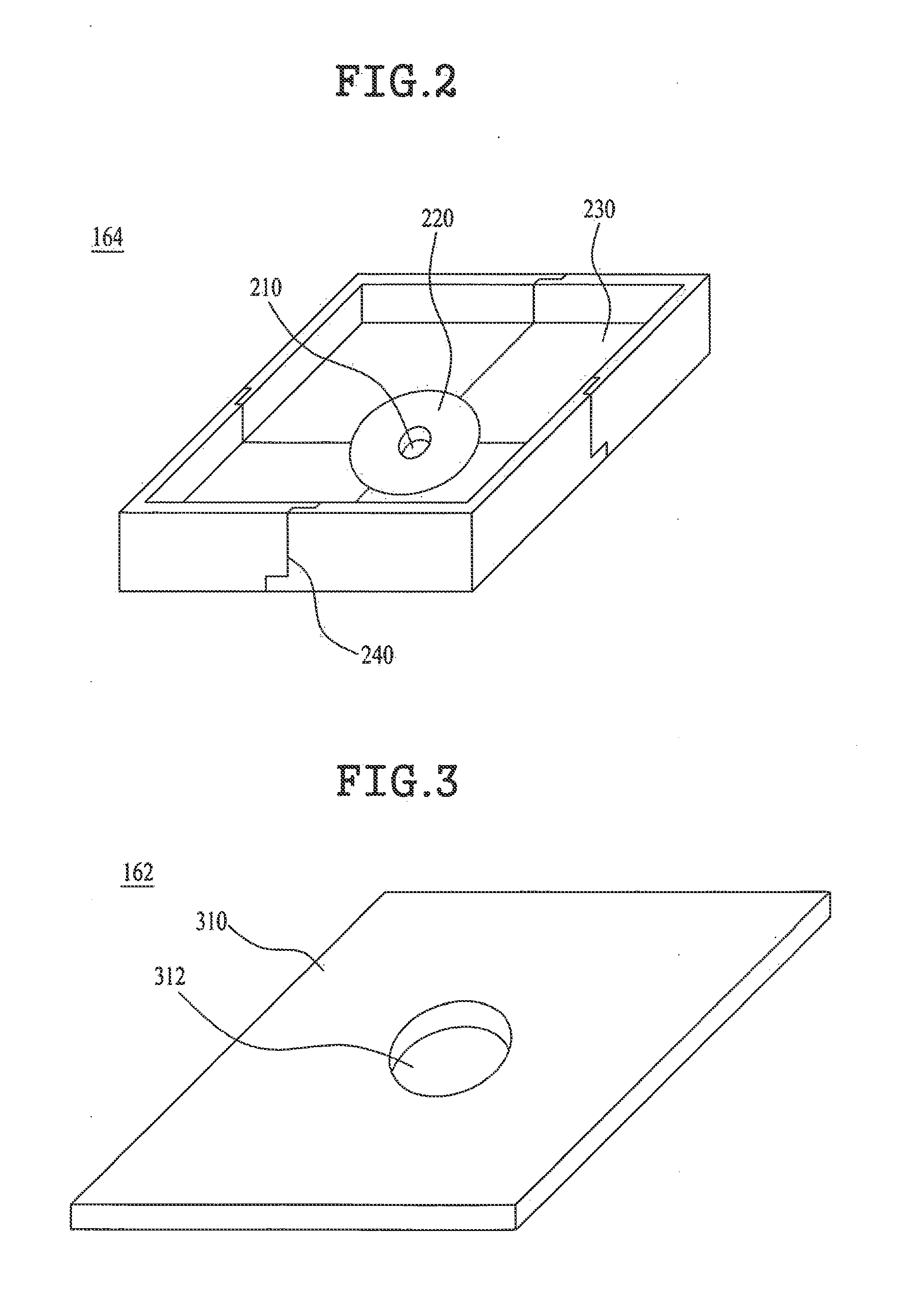
[0062]As shown in FIG. 3, the grounding part 162 according to the present invention may be a rectangular-shaped flat panel 310 with a central hole 312, but it is not limited to this structure. The grounding part 162 may be a circular-shaped flat panel based on the shape of the susceptor 160.
[0063]As shown in FIG. 4, the grounding part 162 according to the first embodiment of the present invention may further include a plurality of openings 314 arranged in a grid configuration. In this case, each opening 314 may be formed in a rectangular shape or a circular shape.
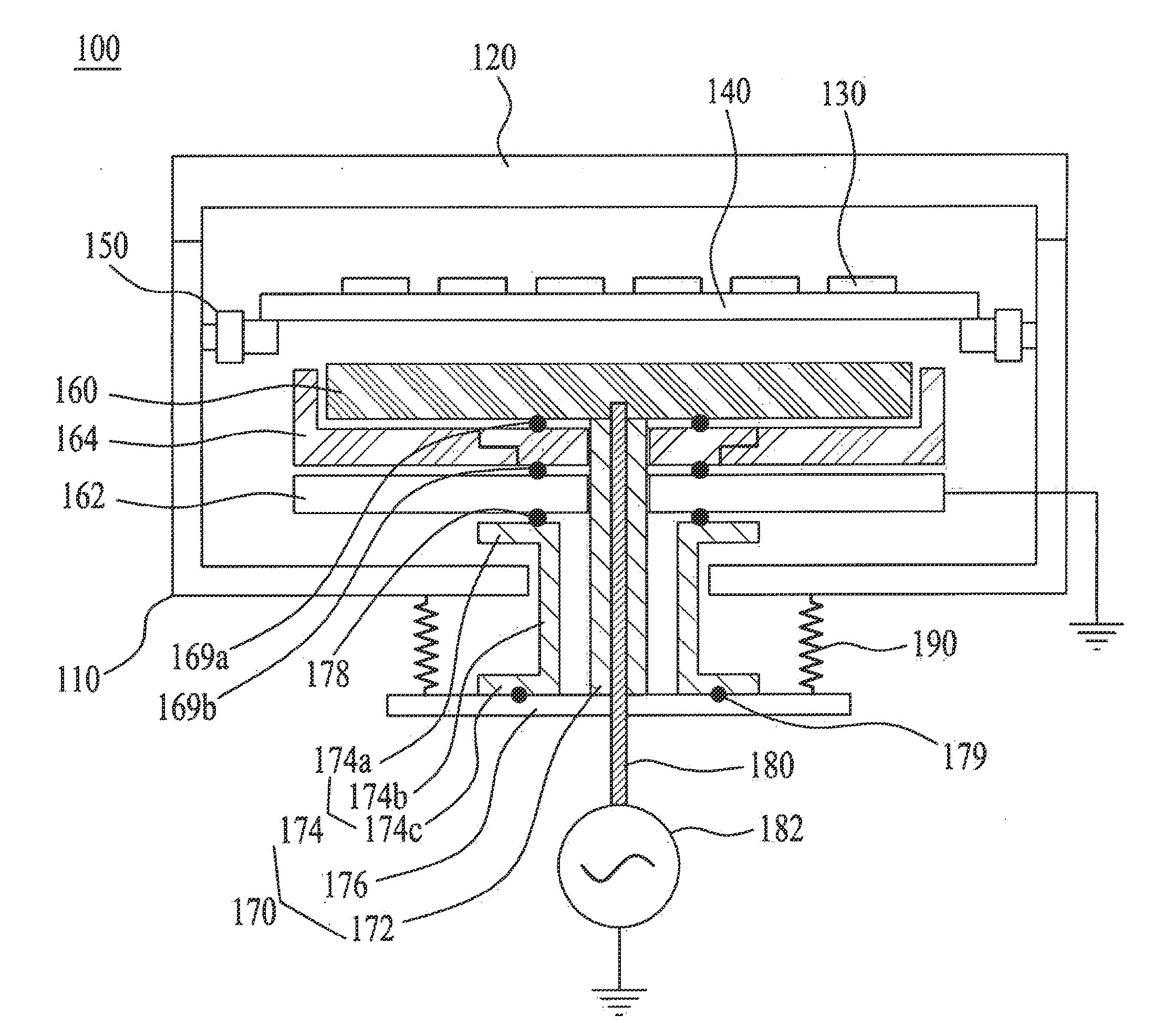
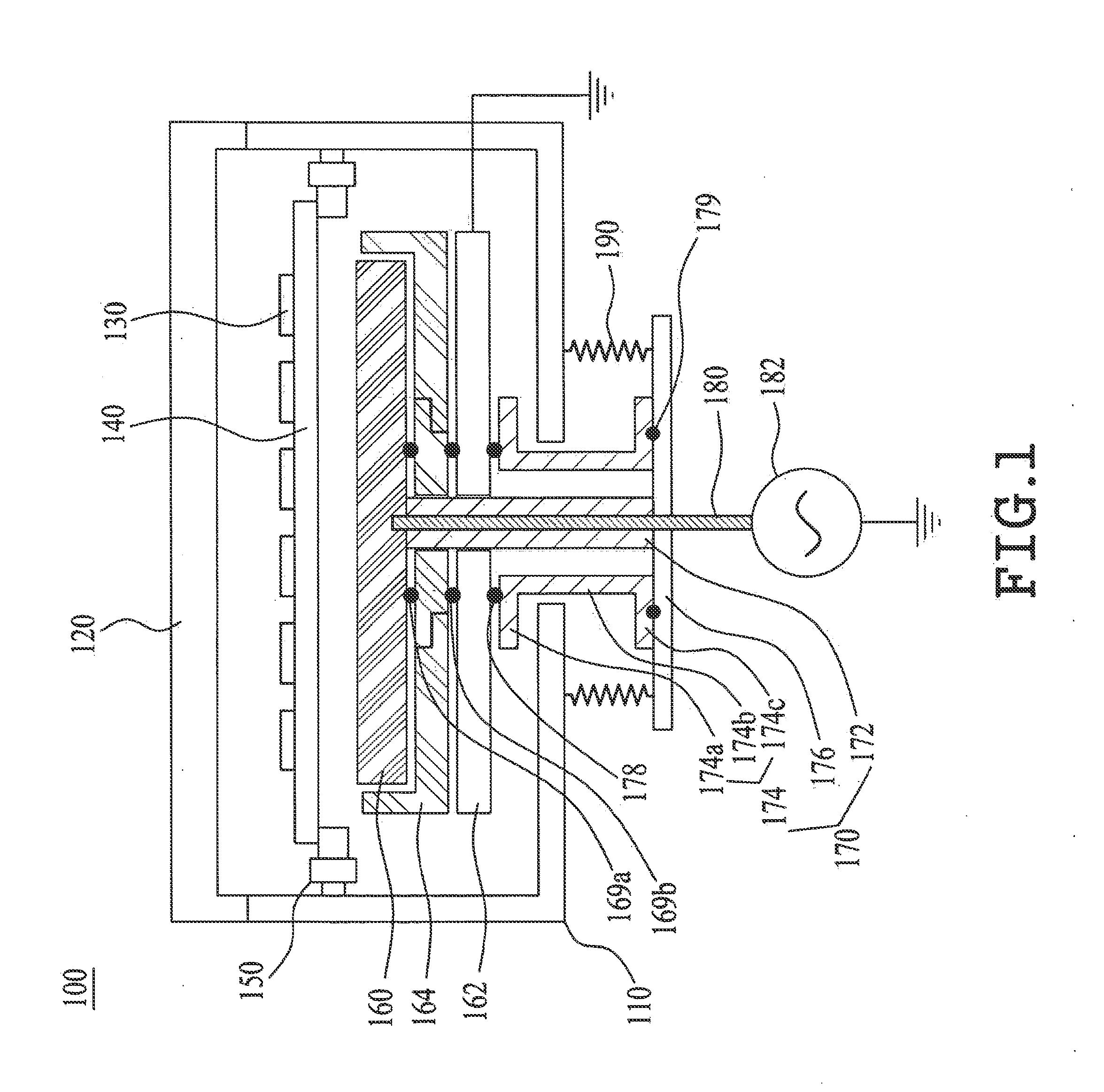
[0064]A first sealing member 169a is provided between the susceptor 160 and the insulating part 164, and a second sealing member 169b is provided between the grounding part 162 and the insulating part 164. In this case, the first and second sealing members 169a and 169b may be respectively O-rings, and the first sealing member 169a may be positioned above the first insulator 220. The first and second sealing members 169a an...
second embodiment
[0077]FIG. 6 illustrates a perspective view for explaining a grounding part according to the present invention.
[0078]Referring to FIG. 6, the grounding part 162 according to the second embodiment of the present invention may be provided with an external frame 410, a central frame 420, and a mesh portion 430.
[0079]The external frame 410 is formed in a rectangular shape corresponding to the edge of the susceptor 160. FIG. 6 illustrates the rectangular-shaped external frame 410, but the shape of the external frame 410 is not limited to the rectangular shape. If the susceptor 160 is formed in a circular shape, the external frame 410 may be formed in the circular shape.
[0080]The central frame 420 is formed in the external frame 410 such that the first supporter 172 passes through the central frame 420. Then, second and third sealing members 169b and 178 may be respectively provided on upper and lower surfaces of the central frame 420 so as to separate the reaction space inside the chambe...
third embodiment
[0082]FIG. 7 illustrates a perspective view for explaining a grounding part according to the present invention.
[0083]Referring to FIG. 7, the grounding part 162 according to the third embodiment of the present invention may be formed in a rectangular-shaped frame to be overlapped with the edge of the susceptor 160. Then, second and third sealing members 169b and 178 may be respectively provided on upper and lower surfaces of the grounding part 162 formed in shape of the rectangular frame so as to separate the reaction space inside the chamber 110 from the external atmospheric space.
PUM
| Property | Measurement | Unit |
|---|---|---|
| thickness | aaaaa | aaaaa |
| frequency | aaaaa | aaaaa |
| shape | aaaaa | aaaaa |
Abstract
Description
Claims
Application Information
 - R&D
- Intellectual Property
- Life Sciences
- Materials
- Tech Scout
- Unparalleled Data Quality
- Higher Quality Content
- 60% Fewer Hallucinations
Browse by: Latest US Patents, China's latest patents, Technical Efficacy Thesaurus, Application Domain, Technology Topic, Popular Technical Reports.
© 2025 PatSnap. All rights reserved.Legal|Privacy policy|Modern Slavery Act Transparency Statement|Sitemap|About US| Contact US: help@patsnap.com


