Liquid ejection device

Inactive Publication Date: 2013-09-05
SEIKO EPSON CORP
View PDF2 Cites 5 Cited by
  • Summary
  • Abstract
  • Description
  • Claims
  • Application Information

AI Technical Summary

Benefits of technology

The present invention improves cooling for an inkjet printer by controlling the impact on spray trajectories. By increasing suction at a remote location (second suction port), the amount of air cooling the irradiation section is increased without affecting the spray trajectory from the nozzle. The adjustment section can change the opening area of the second suction port to control the amount of air sucked. Additionally, the air suction direction in the second suction port can be opposite to the direction in the first suction port to increase the cooling effect. Overall, the invention provides an efficient way to cool the irradiation section while maintaining optimal spray trajectories.

Problems solved by technology

In the above mentioned publication, however, the suction force of the suction fan needs to be controlled so as not to affect spray trajectories of ink drops ejected from the nozzle, which causes a problem that the cooling effect on the irradiation section is insufficient.
Air farther from the nozzle is more difficult to heat by reaction heat or the like due to light curing of the liquid ejected from the nozzle.

Method used


Image

  • Liquid ejection device
  • Liquid ejection device
  • Liquid ejection device

Examples


Embodiment Construction

[0028]Hereinafter, embodiments of the present invention will be explained in the following order: (1) Configuration of Printer; and (2) Modified Embodiment.

(1) Configuration of Printer

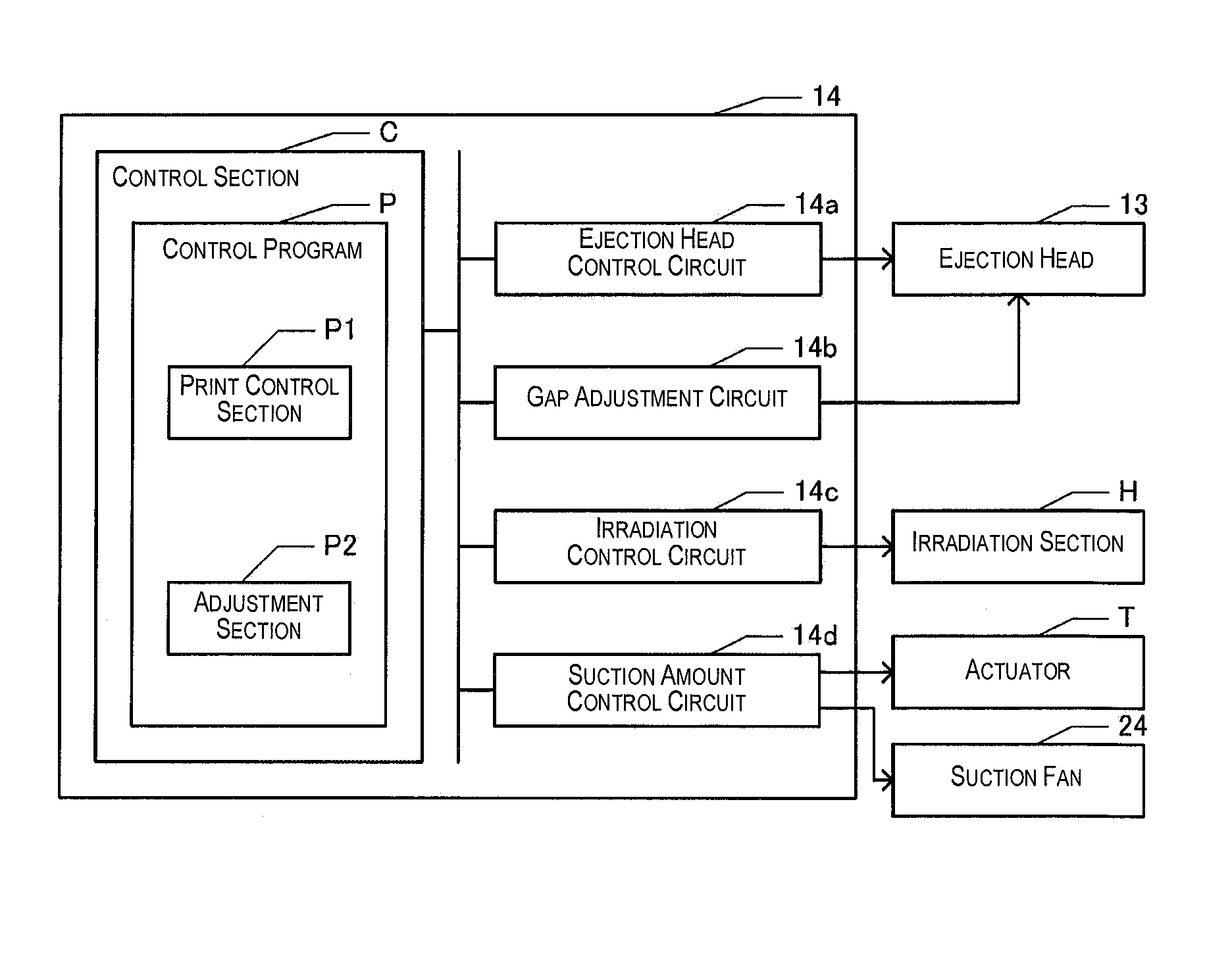
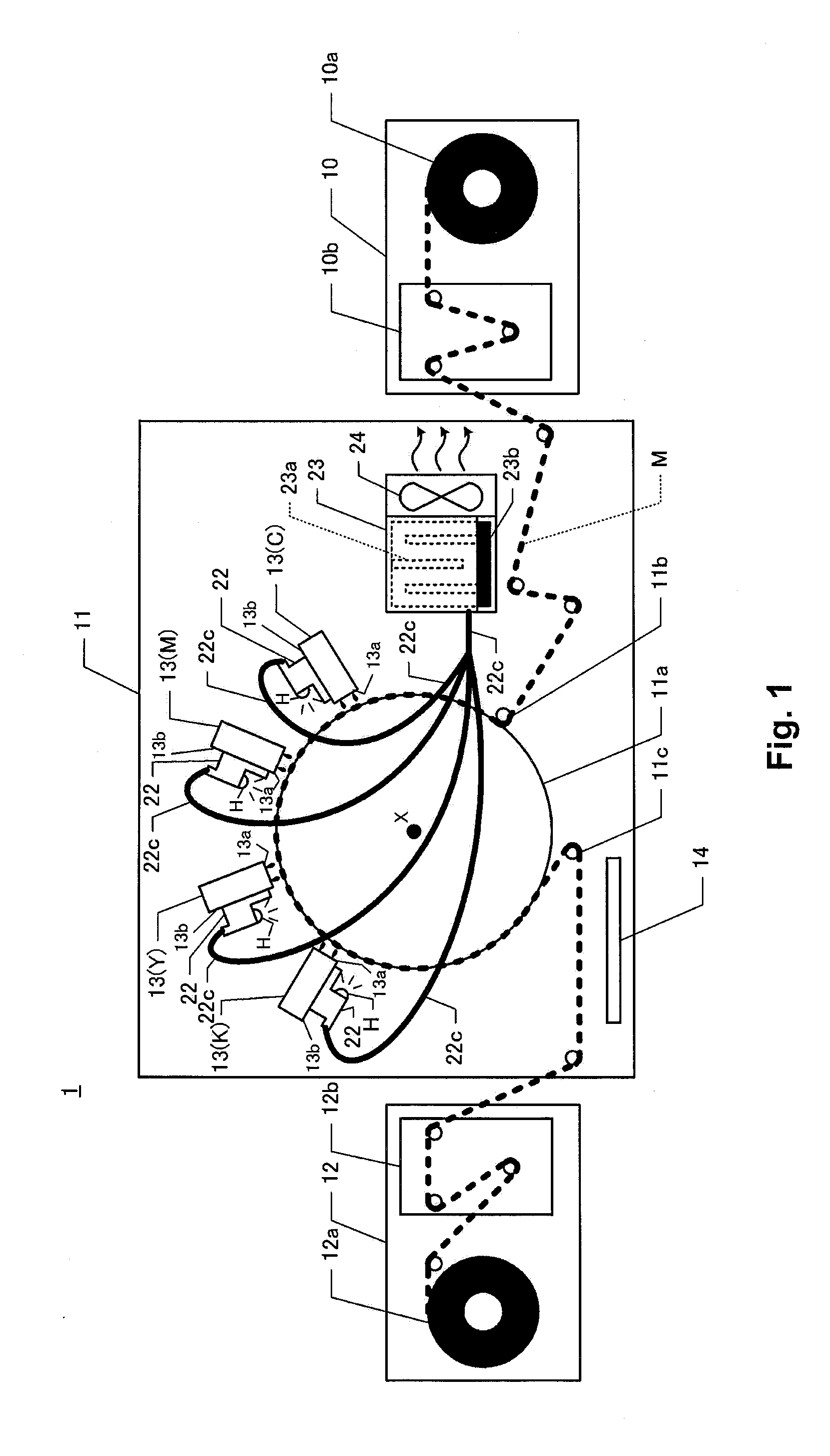
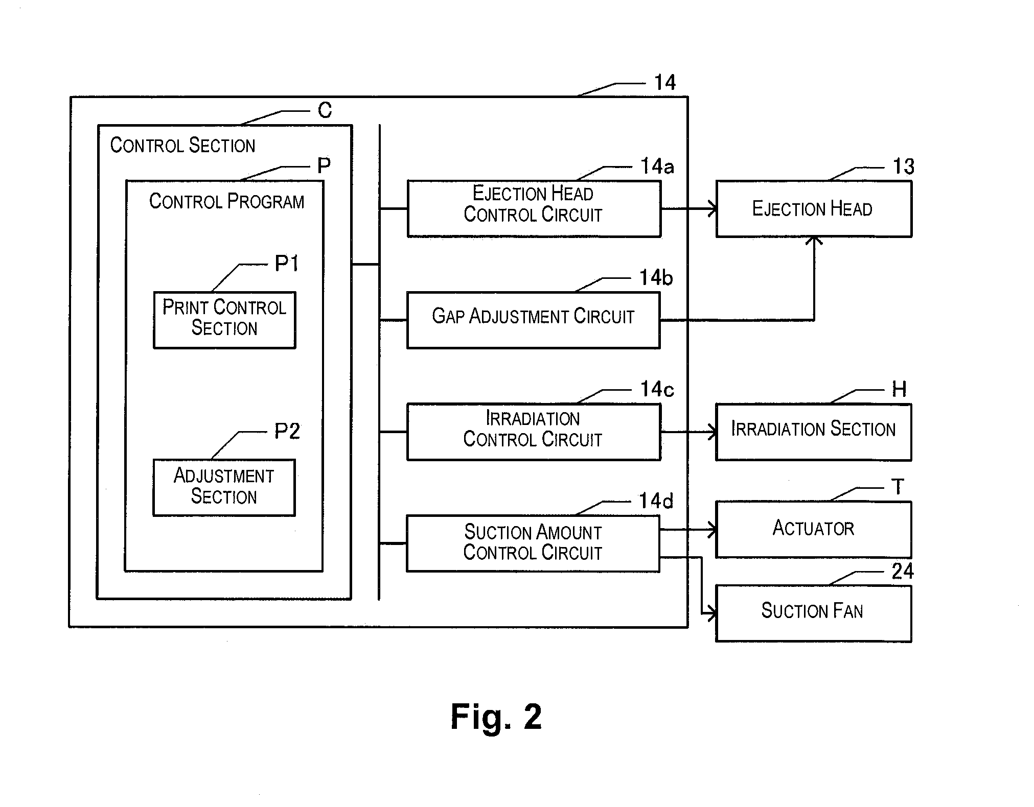
[0029]FIG. 1 is a block diagram showing a configuration of a printer 1 as a liquid ejection device according to an embodiment of the present invention. The printer 1 has a feed section 10, a print section 11, a recovery section 12, an ejection head 13, and a control board 14. The feed section 10 has a feed reel 10a and a tension adjustment section 10b. A roll of paper M is rolled around a roll core of the feed reel 10a, and the roll of paper M is reeled out by rotating the feed reel 10a around a central axis of the roll core. The tension adjustment section 10b has a roller biased to exert prescribed tension on the roll of paper M between the feed reel 10a and the print section 11.

[0030]The print section 11 has a drum 11a, a feed-in roller 11b, and a feed-out roller 11c. The drum 11a is formed to have a...


PUM


Abstract

A liquid ejection device includes: an ejection head configured and arranged to eject liquid from a nozzle; a suction container in which a first suction port, a second suction port that is farther away from the nozzle compared to the first suction port, and a discharge port are formed, air sucked from the first suction port and the second suction port passing through the suction container; and a suction device configured and arranged to suck the air from the discharge port to an outside of the suction container.

Description

CROSS-REFERENCE TO RELATED APPLICATIONS[0001]This application claims priority to Japanese Patent Application No. 2012-047695 filed on Mar. 5, 2012. The entire disclosure of Japanese Patent Application No. 2012-047695 is hereby incorporated herein by reference.BACKGROUND[0002]1. Technical Field[0003]The present invention relates to a liquid ejection device that collects a mist of liquid generated by ejecting liquid from a nozzle.[0004]2. Related Art[0005]A technique for sucking a mist of ink generated by ejecting ink drops having light curing characteristics from a nozzle has been known (see Japanese Laid-Open Patent Publication No. 2009-172937). In Japanese Laid-Open Patent Publication No. 2009-172937, wind for sucking a mist of ink is applied to a heat releasing fin so as to cool an irradiation section that emits light for causing ink to cure. According to this publication, a suction fan for sucking a mist of ink and a suction fan for cooling the irradiation section can be made in ...

Claims


Application Information

Patent Timeline
IPC IPC(8): B41J2/165
CPCB41J11/002B41J2/1652B41J29/377B41J11/0021B41J11/00214
Inventor MASUDA, NORIHIRO
Owner SEIKO EPSON CORP
Why Eureka
Try Eureka