
Display device, display method for same, and liquid crystal display device

a display device and liquid crystal technology, applied in the direction of instruments, computing, electric digital data processing, etc., can solve the problems of deteriorating character of the display device, and achieve the effect of reducing the constant current that flows through keeping the signal line driver circuit running, and driving power

Inactive Publication Date: 2013-08-29
SHARP KK
View PDF17 Cites 27 Cited by
  • Summary
  • Abstract
  • Description
  • Claims
  • Application Information

AI Technical Summary

Benefits of technology

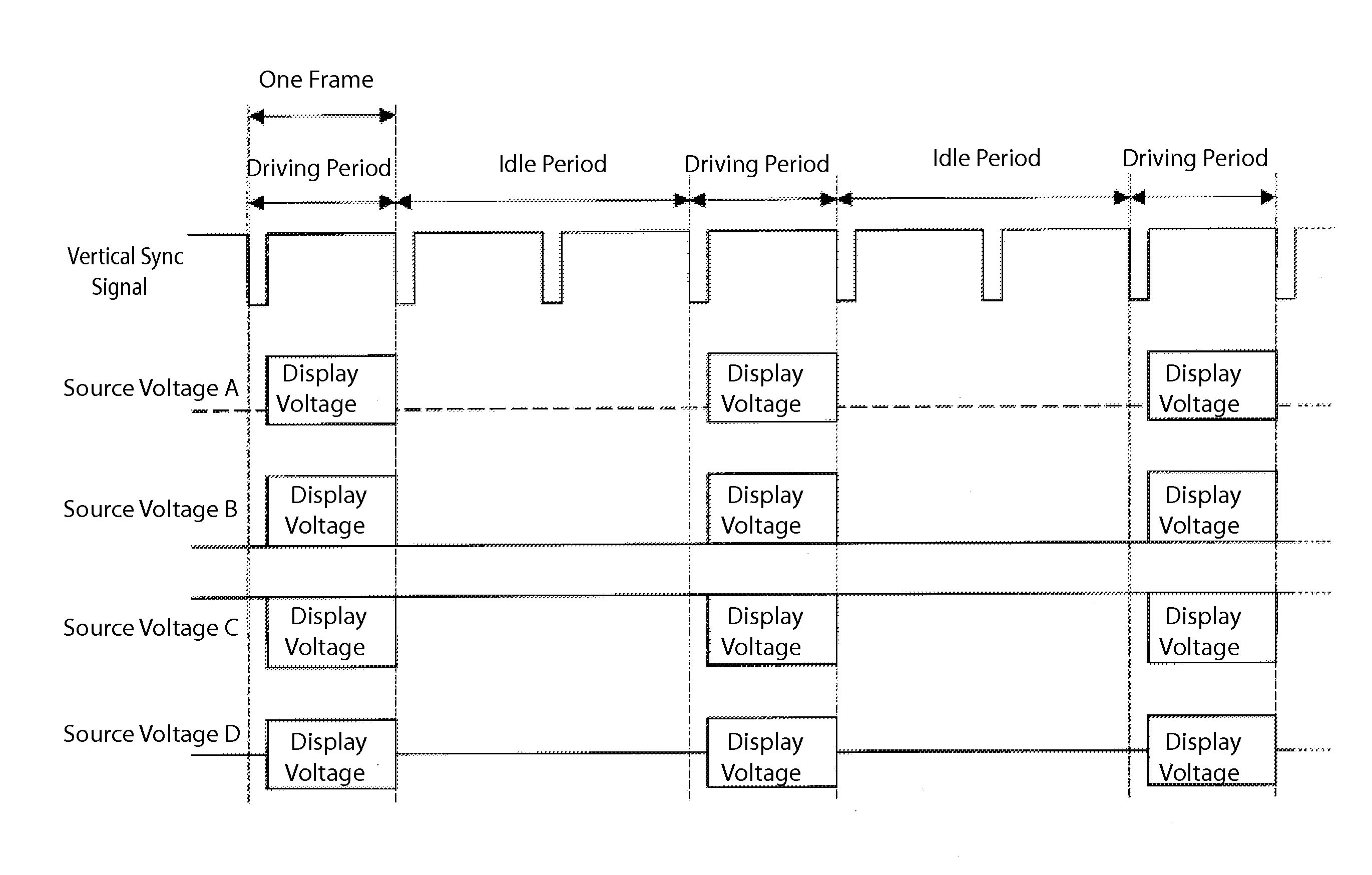
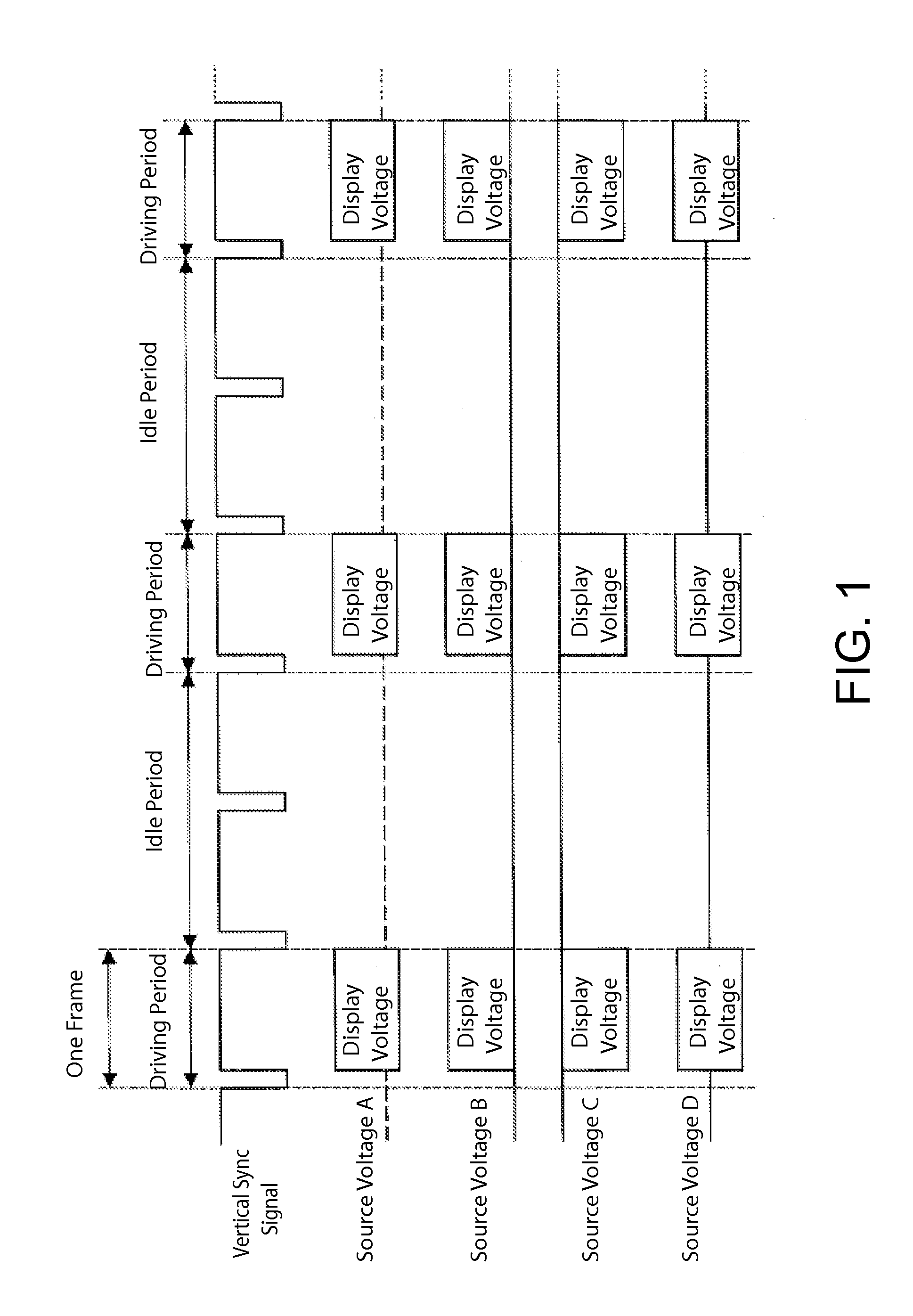
The display device described in this patent reduces power consumption and flickering to achieve a high quality display. It does this by keeping the driving power of the signal line driver circuit low during the idle period to reduce the constant current that flows through the circuit. The data signal lines are also set to have a constant potential during the idle period to prevent potential changes in pixels and flickering. Overall, this technology achieves both a reduction in power consumption and a high quality display.

Problems solved by technology

In driving a liquid crystal display device, if a direct current voltage (DC voltage) is applied to liquid crystal molecules over a long period of time, characteristics thereof are deteriorated.

Method used


Image

  • Display device, display method for same, and liquid crystal display device
  • Display device, display method for same, and liquid crystal display device
  • Display device, display method for same, and liquid crystal display device

Examples


Embodiment Construction

[0026]Below, embodiments of a display device according to the present invention will be explained in details with reference to figures.

[0027](Configuration of Display Device 1)

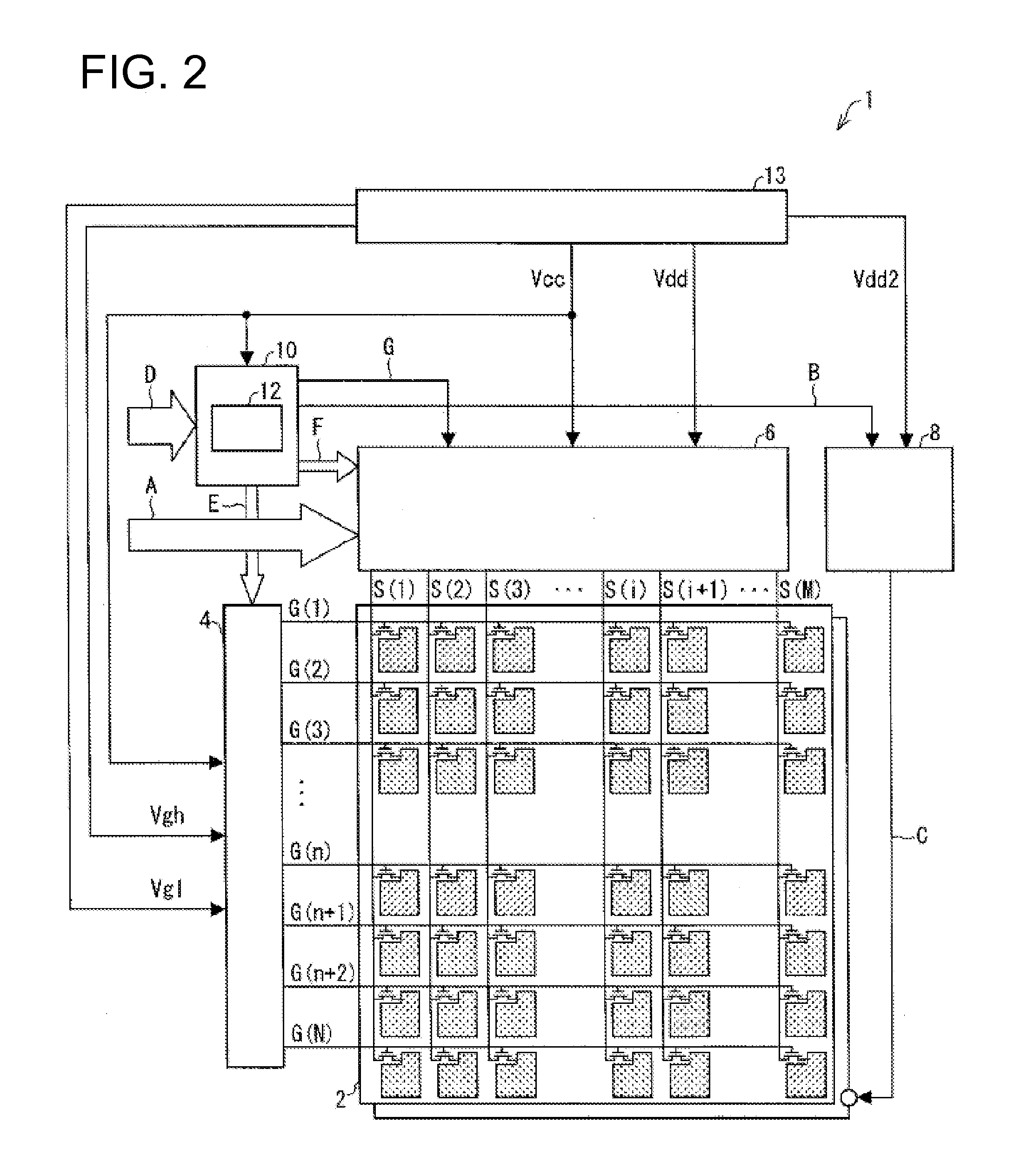
[0028]First, a configuration of a display device 1 (liquid crystal display device) of the present embodiment will be explained with reference to FIG. 2. FIG. 2 is a diagram showing an overall configuration of the display device 1. As shown in the figure, the display device 1 includes a display panel 2, a scanning line driver circuit (gate driver) 4, a signal line driver circuit (source driver) 6, a common electrode driver circuit 8, a timing controller 10, and a power generation circuit 13. The timing controller 10 includes a control signal output part (driving power control unit) 12. The display device 1 is a matrix type display device that is driven by a dot inversion driving method.

[0029]The display panel 2 includes a screen that has a plurality of pixels arranged in a matrix, N (N is an integer) number of ...


PUM


Abstract

When an idle period is started, a voltage of the control signal is changed from a value H to a value L. As a result, the analog amplifiers provided in the signal line driver circuit are switched from the normal state to the low-driving power state. At this time, the data signal lines are set to have a constant potential. A gate voltage is changed from Vgh to Vgl at the same time as when the control signal was changed from the value H to the value L. As a result, the gate of each TFT returns to the OFF state from the ON state. The control signal remains at the value L until the idle period is over. In other words, when the next driving period is started, the voltage of the control signal is changed from the value L to the value H. As a result, the analog amplifiers in the signal line driver circuit are switched back to the normal state from the low-driving power state.

Description

TECHNICAL FIELD[0001]The present invention relates to a display device that performs display by a dot inversion driving method, a display method for the same, and a liquid crystal display device.BACKGROUND ART[0002]In recent years, liquid crystal display devices are rapidly spreading, replacing cathode ray tubes (CRTs). The liquid crystal display devices have advantages of low energy consumption, thin profile, light weight, and the like, and are widely used as display panels for television receivers, personal computers, mobile phones, and the like.[0003]In driving a liquid crystal display device, if a direct current voltage (DC voltage) is applied to liquid crystal molecules over a long period of time, characteristics thereof are deteriorated. Therefore, in order to avoid this problem, a polarity inversion driving method is generally employed such that the polarity of a voltage applied to the liquid crystal molecules is periodically reversed. One of the conventional polarity inversi...

Claims


Application Information

Patent Timeline
Patent Type & Authority Applications(United States)
IPC IPC(8): G09G3/36
CPCG09G3/3614G09G3/3648G09G3/3674G09G2330/021G09G2310/08G09G3/3677G09G2300/0823G09G2320/0247
Inventor NAKATA, JUNSAITOH, KOHJI
Owner SHARP KK
Learn More