
Method for operating a gas discharge lamp of a motor vehicle headlamp

Inactive Publication Date: 2013-08-22
AUTOMOTIVE LIGHTING REUTLINGEN GMBH
View PDF10 Cites 2 Cited by
  • Summary
  • Abstract
  • Description
  • Claims
  • Application Information

AI Technical Summary

Benefits of technology

The invention is about a new method for operating gas-discharge lamps to prevent malfunctions and achieve a symmetrical distribution of electrode polarities. The method uses a logic component and non-volatile memory to store a history of the polarities and can switch between them during operation to ensure a stable and reliable lamp operation even at reduced power levels. By reversing the polarities in a subsequent operating phase, a symmetrical distribution of polarities can be achieved and an alternating pattern of polarity distribution can be followed over the course of multiple operating phases. This prevents one-sided wear to the electrodes and ensures a longer lifespan for the gas-discharge lamp.

Problems solved by technology

The control and transference are accompanied by power loss (released in the control device in the form of heat), leading to a heating thereof and, thereby, leading to a thermal load to the control device.
Thermal loads can have a negative impact on the life expectancy of the control device when they exceed a normal level and, in extreme cases, may lead to a premature malfunction thereof.
An excessive reduction in the AC operation thereof leads to undesired instabilities of the electric arc, which can result in an electric are being extinguished.
It has been shown that gas-discharge lamps, which are frequently operated in a DC mode, malfunction with a greater probability than gas-discharge lamps operated less frequently in the DC mode.
The protection from a thermal overload to the control device, therefore, would appear to be accompanied in the related art with an increase in the chance of a malfunction of the gas-discharge lamp.

Method used


Image

  • Method for operating a gas discharge lamp of a motor vehicle headlamp
  • Method for operating a gas discharge lamp of a motor vehicle headlamp
  • Method for operating a gas discharge lamp of a motor vehicle headlamp

Examples


Embodiment Construction

[0034]The same reference numerals refer in the various figures to the same components or at least to components having the same function.

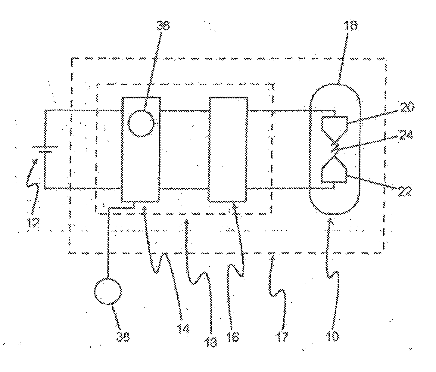
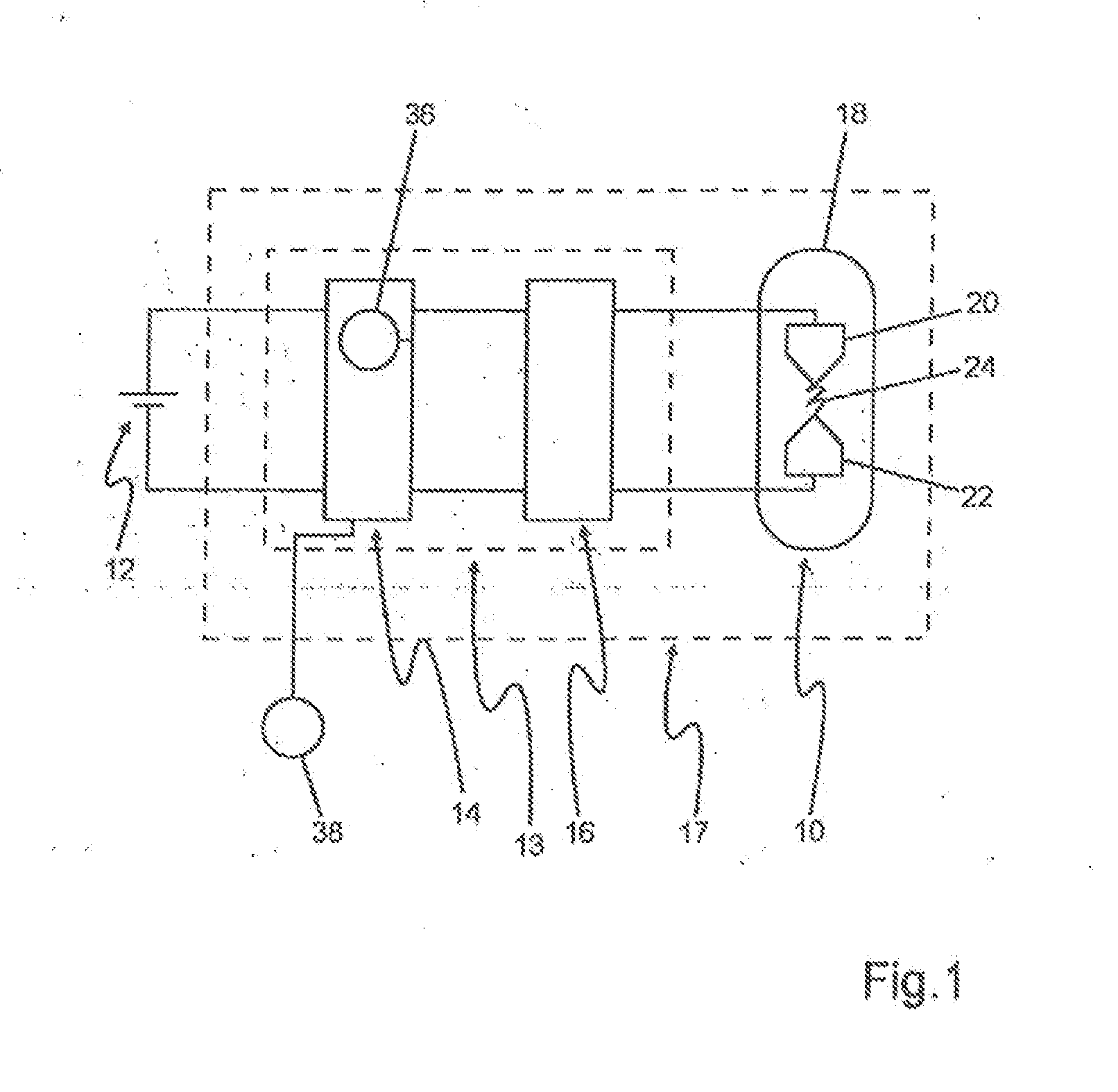
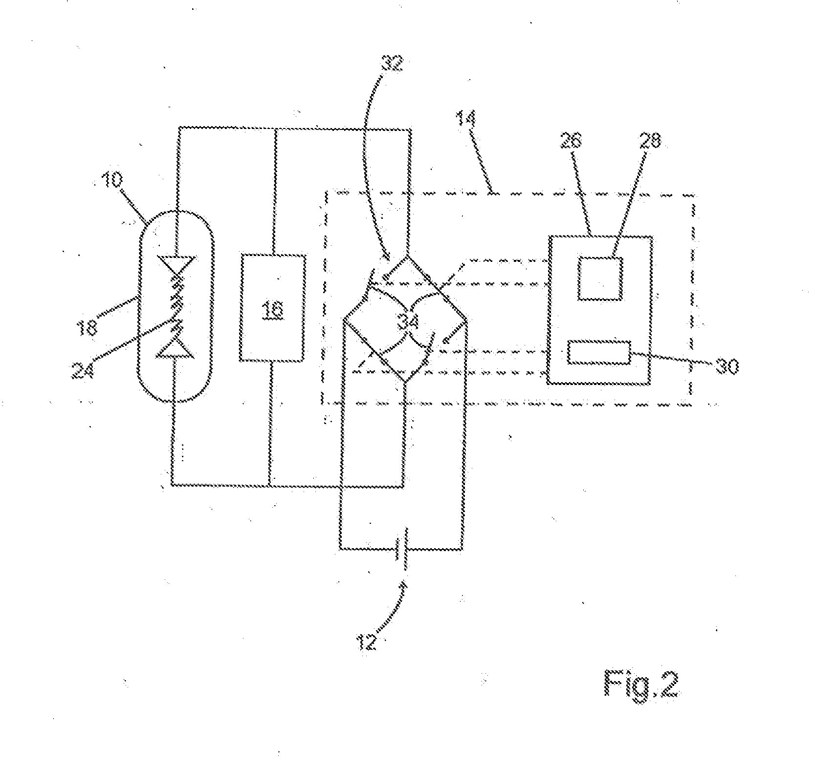
[0035]FIG. 1 shows a gas-discharge lamp 10 having a storage unit 12 for electric energy and a control unit. For this, the control unit is understood to be the structural unit with which the operation of the gas-discharge lamp 10 is controlled. The control unit can be implemented as a separate control device 14, which is connected to the gas-discharge lamp 10 by a separate ignition device 16. In an alternative embodiment, the control unit is a structurally integrated unit comprising a control device 14 and an ignition unit 16 in the form of a power-supply unit 13. It is also possible that the control unit is implemented as a complete module 17 in the form of a structurally integrated unit having a control device 14, an ignition device 16, and a gas-discharge lamp 10.

[0036]A first temperature gauge 36 is disposed in the interior of the control unit f...


PUM


Abstract

A method for operating a gas-discharge lamp (10) of a motor-vehicle headlamp comprises steps of operating the gas-discharge lamp (10) in a first operating mode at a comparatively higher power and alternating-current voltage and in a second operating mode in a temporally limiting manner at a comparatively lower power and direct-current voltage. When a switch is made from the first operating mode to the second operating mode, a polarity of the direct-current voltage is predefined depending on the respective polarities of the direct-current voltage in at least one previous operating phase of the second operating mode. A device or unit operates the gas-discharge lamp and controls a sequence of the method.

Description

CROSS-REFERENCE TO RELATED APPLICATIONS[0001]This is a “national stage” application of International Patent Application PCT / EP2011 / 065600 filed on Sep. 9, 2011, which, in turn, is based upon and claims priority to German Patent Application 10 2010 045 584.9 filed on Sep. 16, 2010.BACKGROUND OF INVENTION[0002]1. Field of Invention[0003]The invention concerns a method for operating a gas-discharge lamp of a motor-vehicle headlamp as well as a control device for such operation.[0004]2. Description of Related Art[0005]Motor-vehicle headlamps are disposed in the front region of a vehicle and serve to illuminate the roadway in front of the vehicle. The gas-discharge lamp serves as a light source, the light of which is distributed in front of the headlamps and, in particular, on the driving surface by the headlamps in the form of a desired light distribution (such as that from a low-beam lamp distribution or a high-beam lamp distribution). Gas-discharge lamps feature a glass bulb filled wi...

Claims


Application Information

Patent Timeline
IPC IPC(8): H05B41/16
CPCH05B41/2928H05B41/16Y02B20/202H05B41/3928Y02B20/00
Inventor NEESER, DOMINIKJOHANN, CHRISTIAN
Owner AUTOMOTIVE LIGHTING REUTLINGEN GMBH
Learn More