
Integrated natural gas powered sofc systems

a fuel cell and natural gas technology, applied in the direction of fuel cells, solid electrolyte fuel cells, electrolytes, etc., can solve the problems of high operating temperature and expensive materials, and low fuel cell performance, so as to achieve high fuel utilization and high performance.

Active Publication Date: 2013-08-15
GEORGIA TECH RES CORP +1
View PDF5 Cites 44 Cited by
  • Summary
  • Abstract
  • Description
  • Claims
  • Application Information

AI Technical Summary

Benefits of technology

The patent describes a new generation of low temperature SOFCs powered by natural gas that combines two fundamentally different systems. The system includes two cell stacks, one based on SOFC-O and the other based on SOFC-H. The system can achieve high performance and high fuel utilization using the combined system. The patent also discusses the use of various metals and supports for catalytic reforming reactions. The technical effects of this patent include improved performance and efficiency of low temperature SOFCs powered by natural gas using a combined system.

Problems solved by technology

However, SOFCs must be economically competitive to be commercially viable and high operating temperatures and expensive materials contribute to cost.
Unfortunately, lowering the operating temperature also lowers the fuel cell performance, as the electrolyte and electrode materials become less conductive and less catalytically active.
Long-term performance of SOFCs also degrades due to poisoning of the cathode by chromium from interconnect layers, deactivation of the conventional anode by carbon deposition, and poisoning by contaminants (e.g., sulfur) in the fuel gas.
However, the reaction products (e.g. H2O) also dilute the fuel.
Further, the high operating temperatures of most oxygen ion conductors adds to cost and degrades system components.
However, direct utilization of carbon-containing fuels is no longer possible with proton-conducting electrolytes because the reforming reactions at the anode are no longer possible.
However, to date, the ideal mixed ionic conductor has not been found.
In addition, U.S. Pat. No. 7,749,626 requires an additional reformer to reform the exhaust gas and additional fuel before they are supplied to the second stack of SOFC, which will increase operational cost to the SOFCs.
Further, combining two SOFC-O cells together is not the most thermodynamically efficient way for SOFC operation because the second stack of SOFC-O cells also requires high operating temperature to achieve better ionic conductivity and overall efficiency.

Method used


Image

  • Integrated natural gas powered sofc systems
  • Integrated natural gas powered sofc systems
  • Integrated natural gas powered sofc systems

Examples


Embodiment Construction

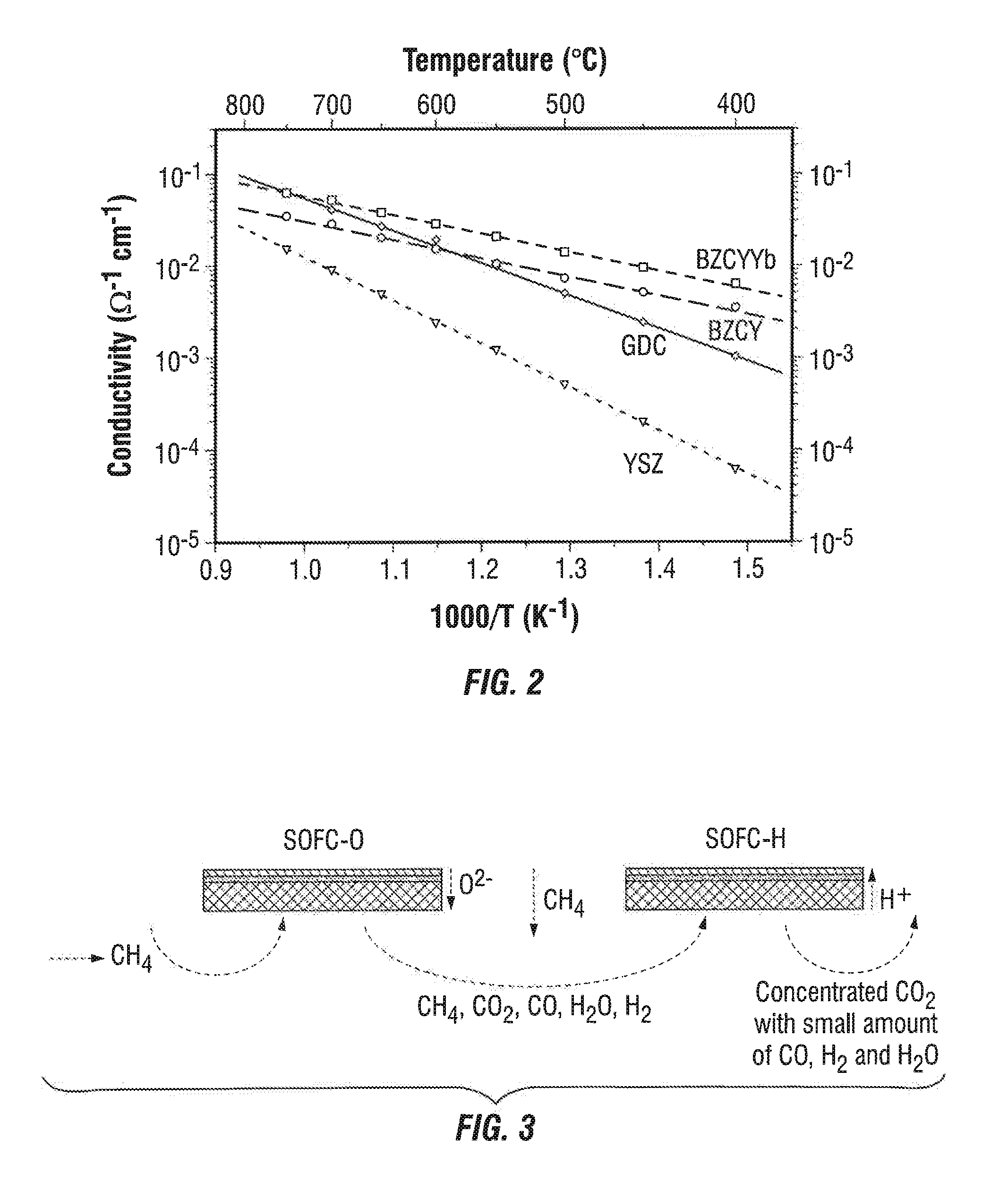
[0042]The invention provides a novel integrated SOFC system that generates power based on using natural gas as the fuel. More specifically, the present invention provides an integrated SOFC system that combines an SOFC-O stack with an SOFC-H stack so as to take advantage of the high operating temperature of the SOFC-O stack by recycling the heat in the reforming process and recycling the exhaust gas from the SOFC-O stack. Both of these features greatly improve the efficiency and cost effectiveness of the battery.

[0043]More particularly, the upstream SOFC-O stack will run at temperatures high enough to electrochemically oxidize the hydrocarbon fuel to generate electricity with the byproduct of CO2 and H2O. Further, the high temperatures of the exhaust and its high CO2 and H2O content will allow H2O and CO2 reforming of hydrocarbon fuels as well as water-gas shift reaction to produce H2 at the downstream SOFC-H stack. The SOFC-H oxidizes the H2 to generate electricity. Yet, the downst...


PUM


Abstract

The present invention discloses an integrated SOFC system powered by natural gas. Specifically, a SOFC-O cell is combined with a SOFC-H cell so as to take advantage of the high operating temperature and steam reforming capabilities of the SOFC-O cell as well as the higher fuel conversion efficiency of the SOFC-H cell.

Description

PRIOR RELATED APPLICATIONS[0001]This application claims priority to 61 / 539,621, filed Sep. 27, 2011, and expressly incorporated by reference herein.FIELD OF THE INVENTION[0002]The invention relates to an integrated natural gas powered solid oxide fuel cell system for generating electricity, and more particularly to an integrated natural gas powered solid oxide fuel cell system in which SOFC-O cells are combined with SOFC-H cells in such a way as to efficiently use lightweight hydrocarbons, e.g., methane, as a fuel source for producing electricity.BACKGROUND OF THE INVENTION[0003]The demand for clean, secure, and renewable energy has stimulated great interest in fuel cells. A fuel cell is a device that converts chemical energy from a fuel into electricity through electrochemical reactions involving oxygen or another oxidizing agent. Fuel cells are different from batteries in that they require a constant source of fuel and oxygen to run, but they can produce electricity continually, s...

Claims


Application Information

Patent Timeline
IPC IPC(8): H01M8/06
CPCY02E60/521H01M8/0606H01M8/0637H01M8/12Y02E60/525H01M16/00H01M2008/1293H01M2300/0074H01M8/2495Y02E60/50H01M8/0618
Inventor LIU, MINGFEILIU, MEILINHE, TING
Owner GEORGIA TECH RES CORP
Learn More