
Electrostatic discharge protection device

a protection device and electrostatic discharge technology, applied in the direction of emergency protective arrangements for limiting excess voltage/current, electrical equipment, semiconductor devices, etc., can solve the problems of mlscr having several shortages in operation that have to be overcome, trigger voltage and holding voltage of mlscr are generally too high or too low, and mlscr is liable to have a latch-up effect, etc., to achieve the effect of enhancing the turn-on speed of ml

Active Publication Date: 2013-08-08
MACRONIX INT CO LTD
View PDF3 Cites 4 Cited by
  • Summary
  • Abstract
  • Description
  • Claims
  • Application Information

AI Technical Summary

Benefits of technology

The electrostatic discharge protection device uses a voltage control circuit to improve the speed at which the device turns on. This is achieved by providing a current path from the control terminal of a modified lateral silicon-controlled rectifier to either the first or second line. This reduces the trigger voltage of the device, which avoids non-uniform turn-on and improves its overall performance. Alternatively, if the voltage control circuit cannot provide a current path, the trigger voltage of the device is increased to prevent a latch-up effect.

Problems solved by technology

However, the MLSCR has several shortages in operation that have to be overcome.
For example, a trigger voltage and a holding voltage of the MLSCR are generally too high or too low.
Moreover, the MLSCR is liable to have a latch-up effect.
In addition, in control of a plurality of the MLSCRs, the MLSCRs are generally unable to be simultaneously turned on, which may cause a non-uniform turn-on phenomenon.
Moreover, a magnitude of the trigger voltage may influence a turn-on speed of the MLSCR.

Method used


Image

  • Electrostatic discharge protection device
  • Electrostatic discharge protection device
  • Electrostatic discharge protection device

Examples


Embodiment Construction

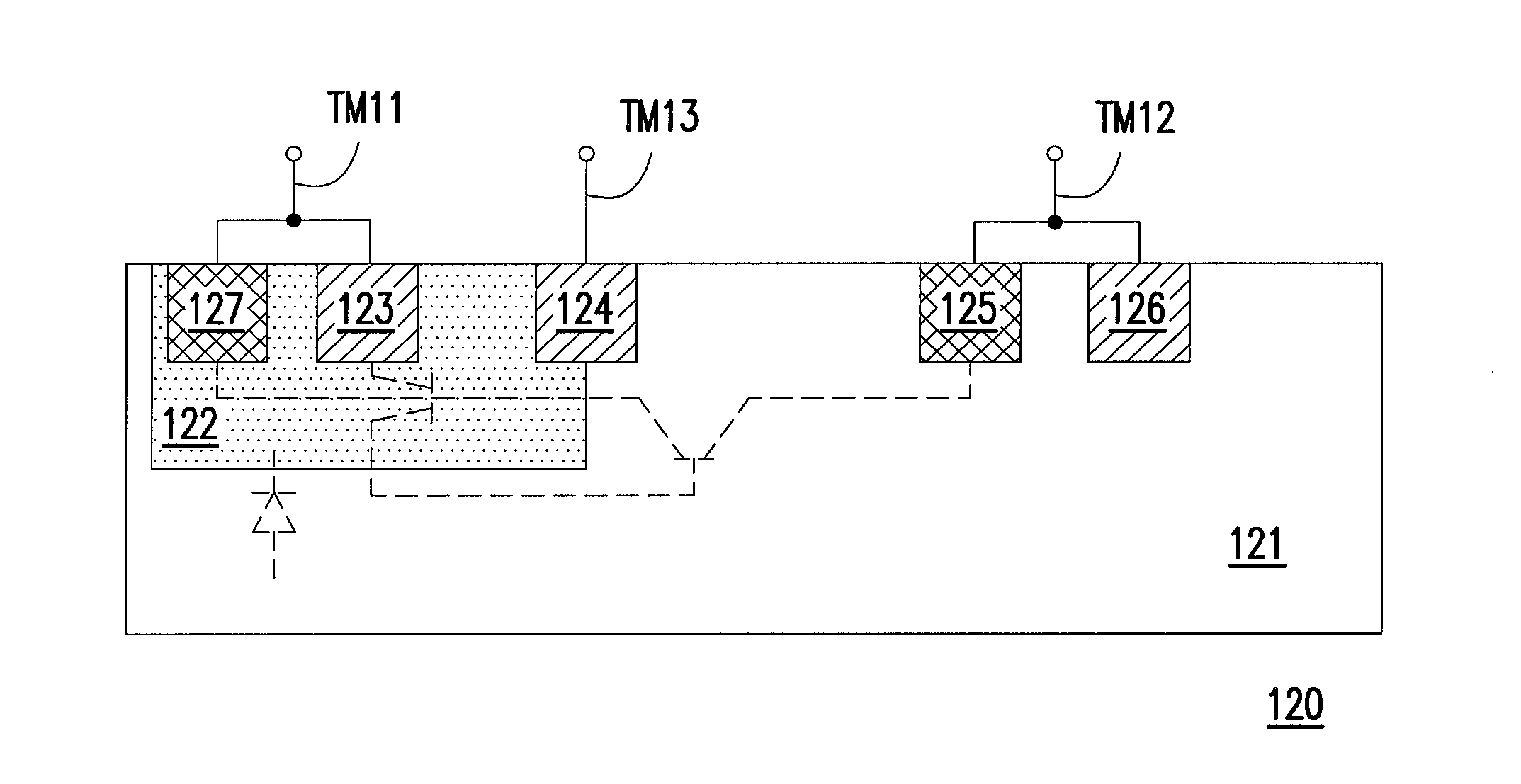
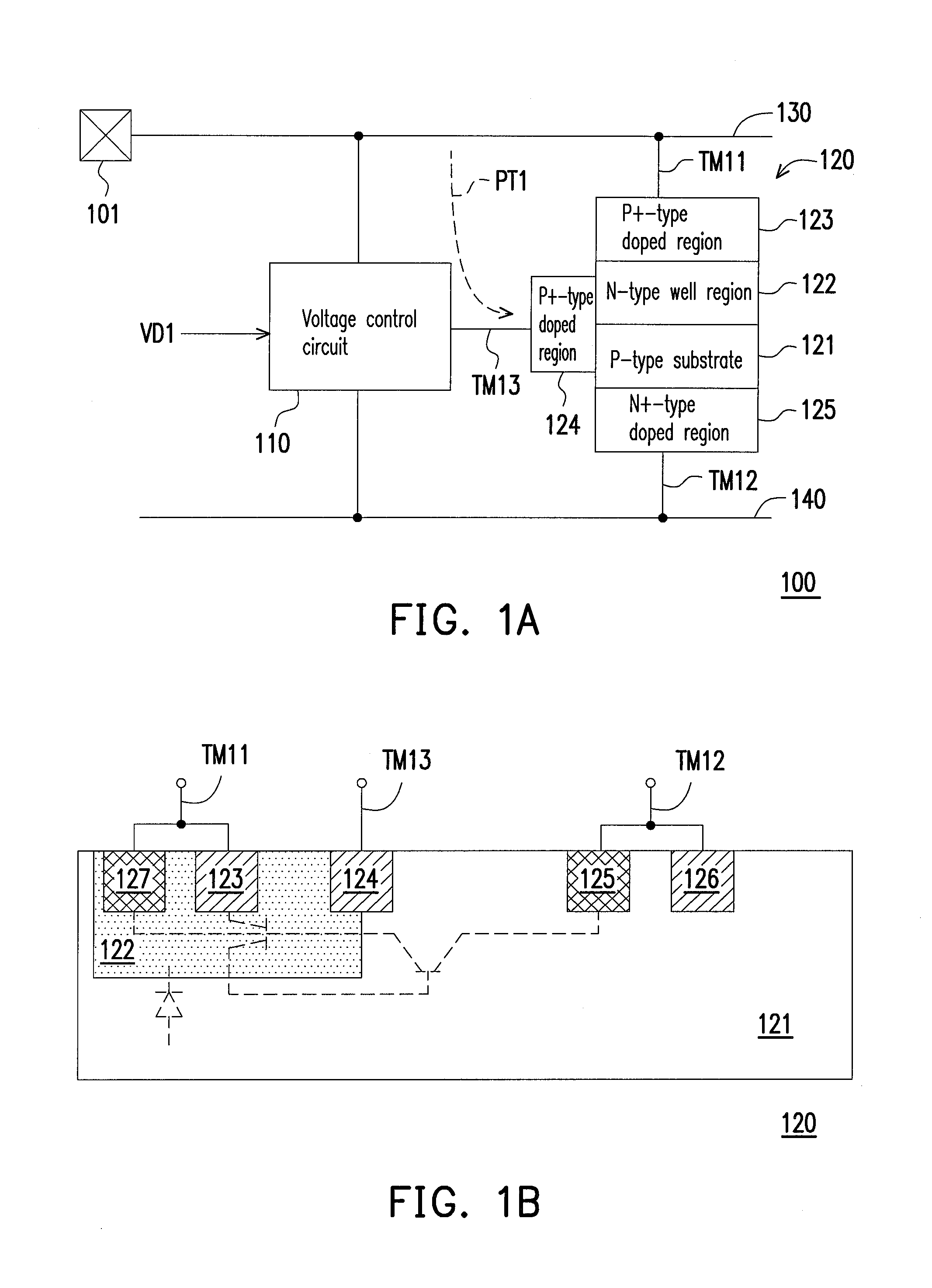
[0025]FIG. 1A is a schematic diagram of an electrostatic discharge (ESD) protection device according to an embodiment of the invention. Referring to FIG. 1A, the ESD protection device 100 includes a voltage control circuit 110 and a modified lateral silicon-controlled rectifier (MLSCR) 120. The MLSCR 120 has a first terminal TM11, a second terminal TM12 and a control terminal TM13. Moreover, FIG. 1B is a cross-sectional view of a layout of the MLSCR according to an embodiment of the invention.

[0026]Referring to FIG. 1B, the MLSCR 120 includes a P-type substrate 121, an N-type well region 122, a P+-type doped region 123, a P+-type doped region 124, an N+-type doped region 125, a P+-type doped region 126 and an N+-type doped region 127. The N-type well region 122 is disposed in the P-type substrate 121. The P+-type doped region 123 and the N+-type doped region 127 are disposed in the N-type well region 122, and are electrically connected to the first terminal TM 11. The P+-type doped ...


PUM


Abstract

An electrostatic discharge (ESD) protection device including a modified lateral silicon-controlled rectifier (MLSCR) and a voltage control circuit is provided. The MLSCR has a first terminal, a second terminal and a control terminal connected to a first P+-type doped region, where the first terminal and the second terminal are electrically connected to a first line and a second line, respectively. The voltage control circuit is electrically connected to the first line, the second line and the control terminal. When an electrostatic pulse is appeared on the first line, the voltage control circuit provides a current path from the first line to the control terminal. When an input signal is supplied to the first line, the voltage control circuit receives a power voltage, and stops providing the current path according to the power voltage.

Description

BACKGROUND OF THE INVENTION[0001]1. Field of the Invention[0002]The invention relates to an electrostatic discharge (ESD) protection device. Particularly, the invention relates to an ESD protection device having a modified lateral silicon-controlled rectifier (MLSCR).[0003]2. Description of Related Art[0004]Electrostatic discharge (ESD) is generally a main reason to cause electrostatic overstress or permanent damage of an integrated circuit (IC), so that an ESD protection device is generally added to the IC to prevent ESD damage. In recent years, a modified lateral silicon-controlled rectifier (MLSCR) has become a basic component in design of the ESD protection device. However, the MLSCR has several shortages in operation that have to be overcome.[0005]For example, a trigger voltage and a holding voltage of the MLSCR are generally too high or too low. Moreover, the MLSCR is liable to have a latch-up effect. In addition, in control of a plurality of the MLSCRs, the MLSCRs are general...

Claims


Application Information

Patent Timeline
IPC IPC(8): H02H9/04
CPCH02H9/046H01L27/0248
Inventor HE, CHIEH-WEIWANG, SHIH-YU
Owner MACRONIX INT CO LTD
Learn More