
Zero-crossing-based analog-to-digital converter having current mismatch correction capability

a zero-crossing-based analog-to-digital converter and current mismatch technology, applied in analogue/digital conversion, instruments, transmission systems, etc., can solve problems such as saturation distortion, distortion, and increase the difficulty of using an operation amplifier to design, so as to eliminate the signal dependence of voltage variations, eliminate saturation distortion, and achieve the effect of reducing the sampling rate of the fully differential zero-crossing-based circui

Inactive Publication Date: 2013-08-08
NATIONAL CHUNG CHENG UNIV
View PDF4 Cites 15 Cited by
  • Summary
  • Abstract
  • Description
  • Claims
  • Application Information

AI Technical Summary

Benefits of technology

The patent describes a new design for an analog-to-digital converter that can improve the resolution, energy efficiency, and sampling rate of a circuit. It uses a current supply separation technique and a digital correction mechanism to correct mismatch among a plurality of current supplies. The design includes a sub-analog-to-digital converter, a current supply branch circuit, a current mismatch correction circuit, and a zero-crossing detector circuit. The technical effect of the design is to improve the accuracy and performance of the analog-to-digital converter.

Problems solved by technology

However, with the CMOS specification requiring reduction in size, increased elements per unit area of chip, and low operation voltage, it has become increasingly difficult to use an operation amplifier to design a switching capacitor circuit convenient to use, to achieve high gain and large output amplitude slew, while maintaining its stability.
However, the mismatch between the Zero Crossing Detector (ZCD) and the current supply could lead to the problem of distortion.
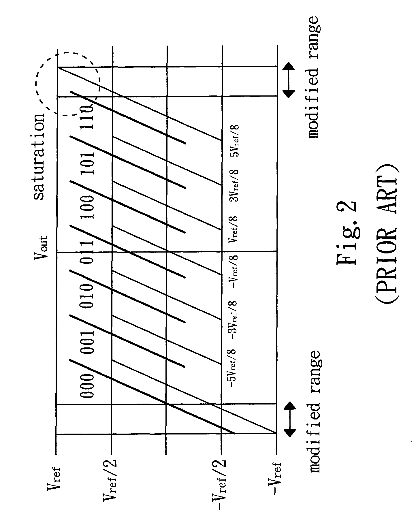
The reason for this is that, the intrinsic non-zero time delay existing in the Zero Crossing Detector (ZCD) could cause over-charge, to produce offset error in pipeline circuit stage, that could result in saturation distortion when a multiplying digital-to-analog conversion circuit (MDAC) outputs it remainder.
Therefore, presently, the design and performance of zero-crossing-based analog-to-digital conversion circuit of the prior art is not quite satisfactory, and it has much room for improvements.

Method used


Image

  • Zero-crossing-based analog-to-digital converter having current mismatch correction capability
  • Zero-crossing-based analog-to-digital converter having current mismatch correction capability
  • Zero-crossing-based analog-to-digital converter having current mismatch correction capability

Examples


Embodiment Construction

[0025]The purpose, construction, features, functions and advantages of the present invention can be appreciated and understood more thoroughly through the following detailed description with reference to the attached drawings. And, in the following, various embodiments are described in explaining the technical characteristics of the present invention.

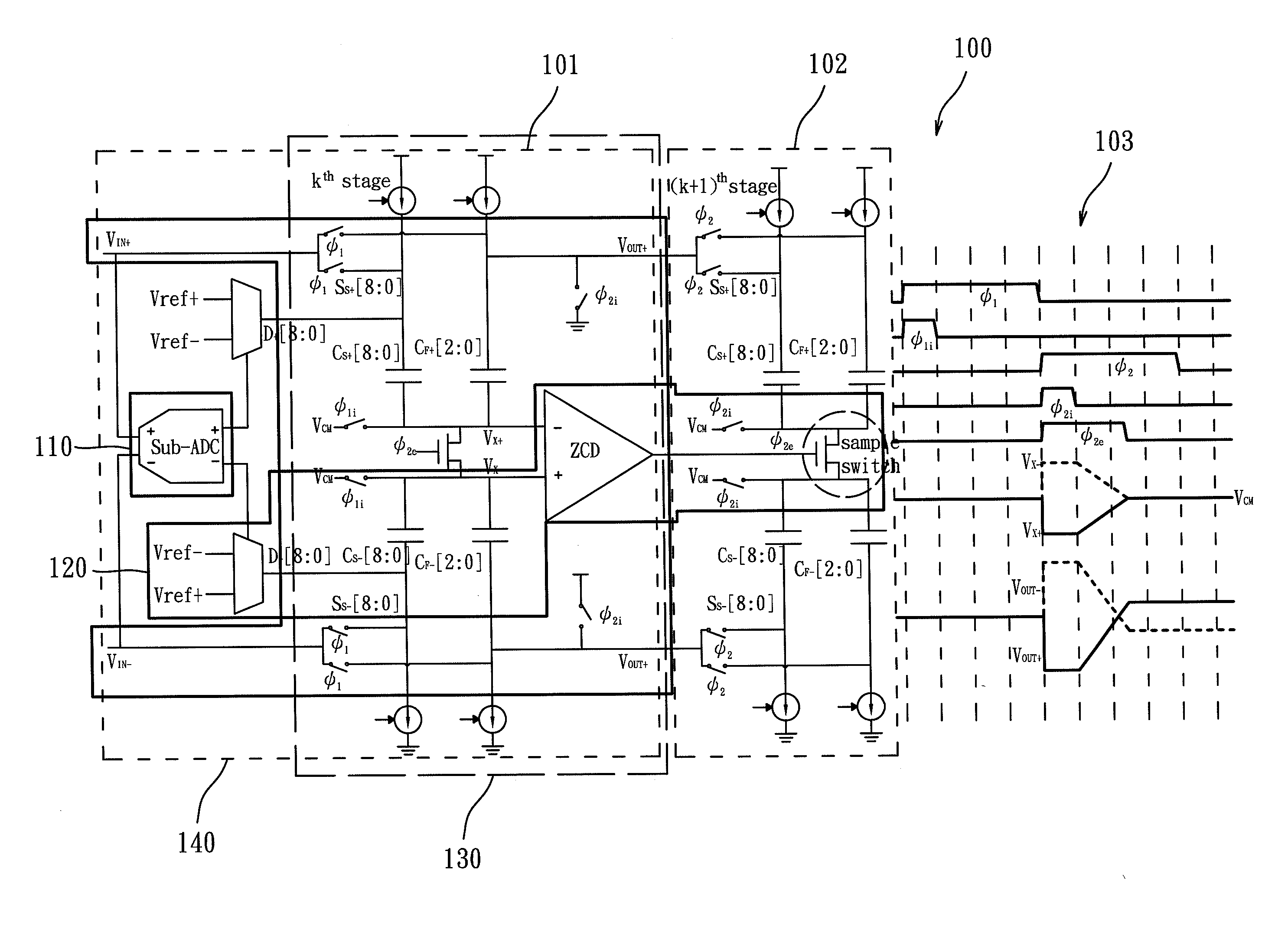
[0026]The present invention provides a zero-crossing-based analog-to-digital converter having current mismatch correction capability. As shown in FIG. 1, the analog-to-digital converter 100 of the present invention adopts a fully differential pipeline design, comprising at least: a kth stage pipeline circuit 101 (abbreviated as the kth stage circuit), and a (k+1)th stage pipeline circuit 102 (abbreviated as the (k+1)th stage circuit). Their relative actions are as shown in a time sequence diagram 103. It has to be noted that, according to the circuit design of the present invention, the analog-to-digital converter 100 can be designed to...


PUM


Abstract

A zero-crossing-based analog-to-digital converter having current mismatch correction capability, that can raise resolution, energy efficiency, and sampling rate of a fully differential zero-crossing circuit, is realized through a 90 nm CMOS technology. The circuit is used mainly to correct offset error, to use a current supply separation technology and a digital correction mechanism to correct mismatch among a plurality of current supplies.

Description

BACKGROUND OF THE INVENTION[0001]1. Field of the Invention[0002]The present invention relates to an analog-to-digital converter, and in particular to a zero-crossing-based analog-to-digital converter having current mismatch correction capability.[0003]2. The Prior Arts[0004]In circuit designs, a negative feedback operation amplifier circuit having high gain, fast response speed, and small and steady current, is often used to realize a pipeline circuit of high resolution, fast sample rate, and low power consumption. However, with the CMOS specification requiring reduction in size, increased elements per unit area of chip, and low operation voltage, it has become increasingly difficult to use an operation amplifier to design a switching capacitor circuit convenient to use, to achieve high gain and large output amplitude slew, while maintaining its stability.[0005]In this respect, a zero-crossing-based pipeline analog-to-digital conversion circuit was proposed in 2007, to replace the o...

Claims


Application Information

Patent Timeline
Patent Type & Authority Applications(United States)
IPC IPC(8): H03M1/12
CPCH03M1/0682H03M1/164H03M1/1023
Inventor TSAI, TSUNG-HENGHSU, PEI-JUNGSHIU, BO-YU
Owner NATIONAL CHUNG CHENG UNIV
Learn More