
Crimped terminal wire for automobile

Inactive Publication Date: 2013-08-08
AUTONETWORKS TECH LTD +2
View PDF8 Cites 24 Cited by
  • Summary
  • Abstract
  • Description
  • Claims
  • Application Information

AI Technical Summary

Benefits of technology

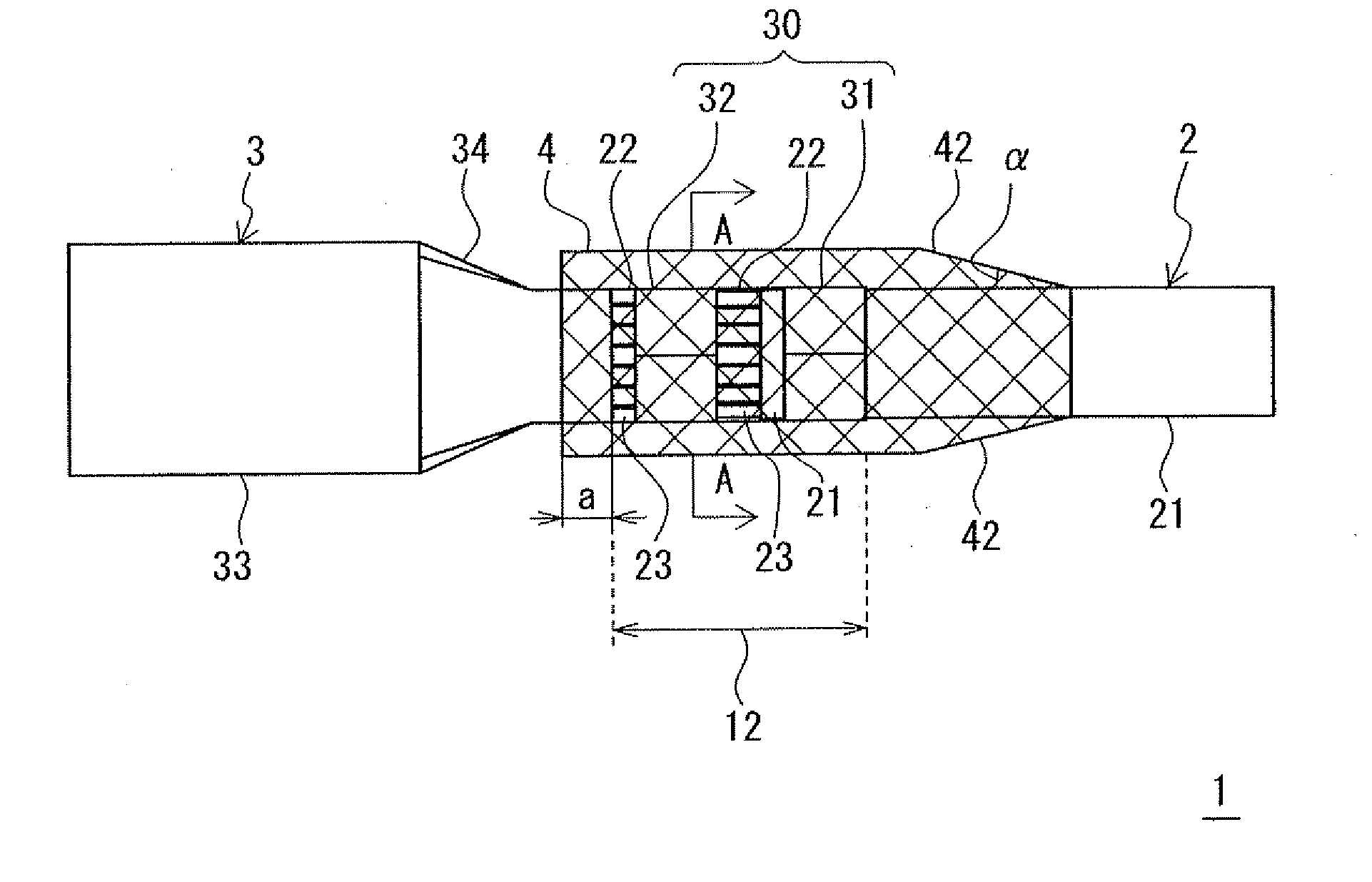
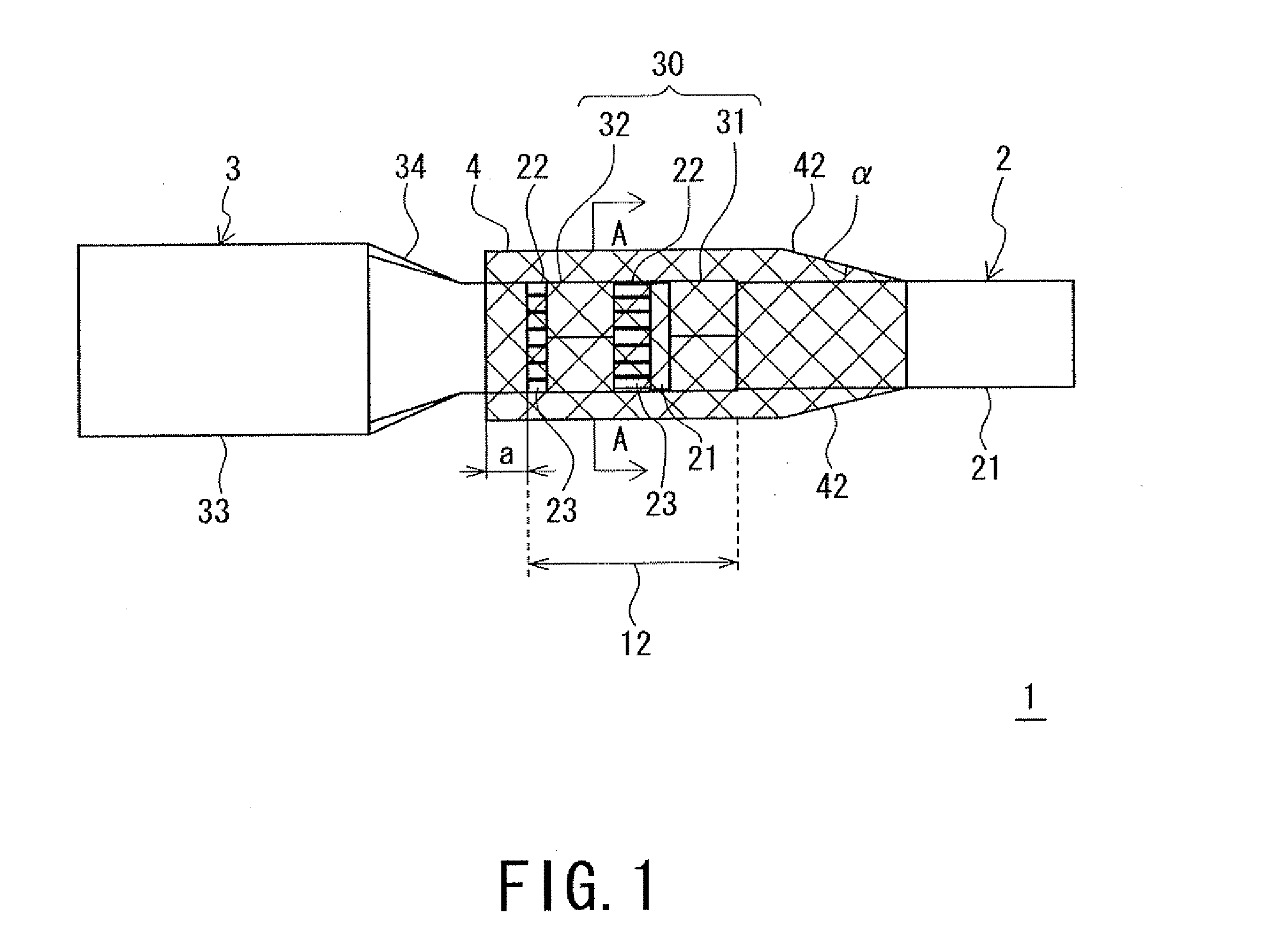
The crimped terminal wire for automobile described in this patent is coated with a resin-coated portion that prevents corrosion from reaching the area where the aluminum electric wire and the connecting terminal meet. This results in a stable and effective prevention of corrosion in the aluminum conductor wire.

Problems solved by technology

When ionization of the aluminum electric wires, which are electrically base, proceed to promote the corrosion as described above, the contact states of the crimped terminal portions become worse, which could make the electrical characteristics of the crimped terminal portions unstable, could increase contact resistance, could increase electrical resistance because of the reduced wire diameters, and could break the electric wires.
Consequently, the electrical components could malfunction, or could break down.

Method used


Image

  • Crimped terminal wire for automobile
  • Crimped terminal wire for automobile
  • Crimped terminal wire for automobile

Examples


example 1 (

Samples No. 1 to 16)

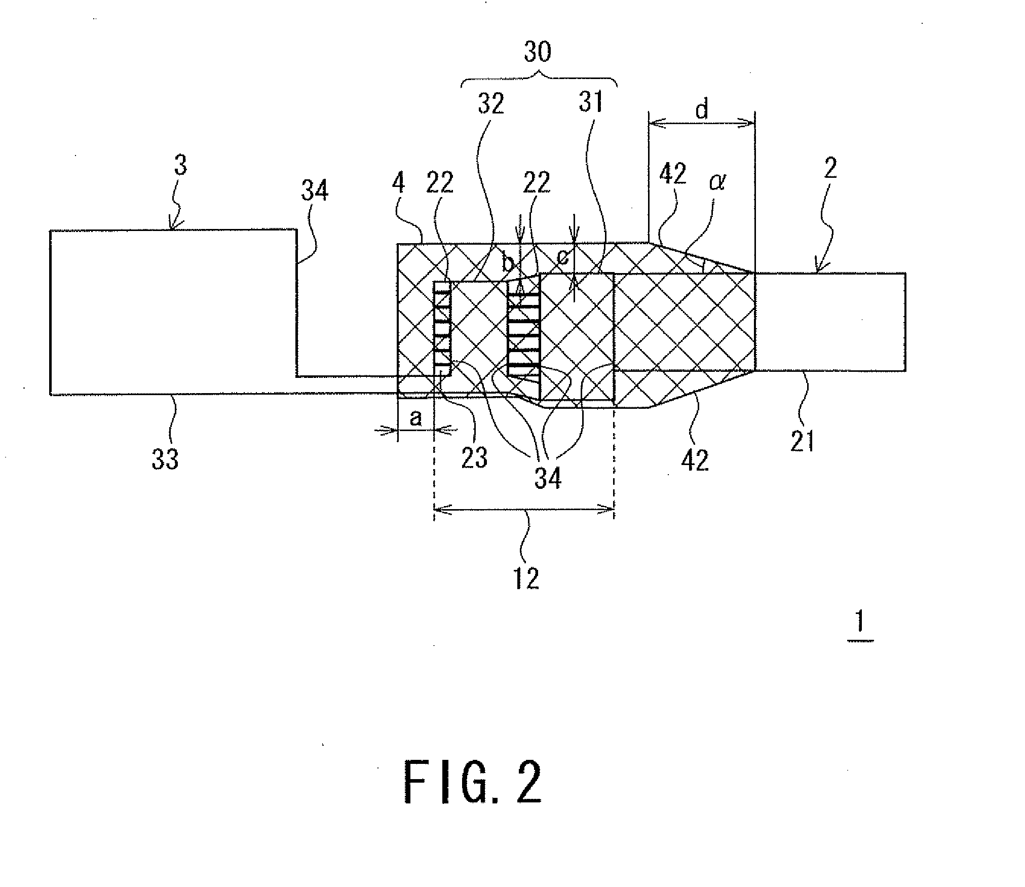
[0043]Crimped terminal wires 1 of samples 1 to 16 of Example 1 were prepared as follows: the crimped terminal wires 1 were prepared, each of which included a connecting terminal 3, which defined a 090 female connecting terminal, an aluminum electric wire 2, which defined an aluminum electric wire 0.75 mm2 or 2.5 mm2 in diameter, and a resin-coated portion 4, which was made from a polyamide resin (manuf.: HENKEL JAPAN LTD., trade name: “MACROMELT 6202”), such that the lengths a of the portions between the top ends of the aluminum conductor wires 23 and the top ends of the resin-coated portions 4, the thicknesses b of the portions of the resin-coated portions 4 with which the upper sides of the conductor-wire portions 22 were coated, and the thicknesses c of the portions of the resin-coated portions 4 with which the cutting faces of the connecting terminals 3 were coated, which were shown in FIG. 1, were varied among the crimped terminal wires 1. Corrosion tests (J...

example 2 (

Samples No. 17 to 30)

[0046]Next, crimped terminal wires 1 of samples 17 to 30 of Example 2 were prepared. The crimped terminal wires 1 of samples 17 to 28 were provided with the resin-coated portions 4 including tapered portions 42 at their posterior end portions. The crimped terminal wires 1 of samples 29, 30 were provided with the resin-coated portions 4 including no tapered portion 42. Bending tests were carried out on the crimped terminal wires 1 of samples 17 to 30. After the tests, the crimped terminal wires 1 of samples 17 to 30 were checked as to the degrees of peeling of the resin coats of the resin-coated portions 4 from the aluminum electric wires 2. The lengths of the tapered portions 42 were expressed as d, and the rising angles of the tapered portions 42 were expressed as α. The crimped terminal wires 1 were bent while held at the portions that were three centimeters behind the posterior ends of the insulation barrels 31 and the electrical contact portions 33 of the co...


PUM


Abstract

To provide a crimped terminal wire for automobile that includes an aluminum electric wire, a connecting terminal made from a copper-based material, and a resin-coated portion that is provided in a range capable of inhibiting crevice corrosion that builds up in a crevice between the connecting terminal and a resin from reaching a bimetal contact portion between the aluminum electric wire and the connecting terminal. A crimped terminal wire for automobile includes an aluminum electric wire, a connecting terminal made from a copper-based material, crimped onto an end of the wire and including a crimped member, a crimped portion where the terminal is crimped onto the wire, and a resin-coated portion disposed on the crimped portion, wherein the resin-coated portion is disposed on the crimped portion while an entire periphery of the crimped portion is coated with the resin-coated portion.

Description

TECHNICAL FIELD[0001]The present invention relates to a crimped terminal wire for automobile that includes an aluminum electric wire, and a connecting terminal that is crimped onto the end of the aluminum electric wire.BACKGROUND ART[0002]In the field of electric power industry, aluminum electric wires, which include conductor wires made from aluminum-based materials that are light in weight and excellent in electrical conductivity, are conventionally used as overhead power lines. Meanwhile, in the field of automobile industry, copper electric wires, which include conductor wires made from copper-based materials that are excellent in electrical conductivity and in cost efficiency, are conventionally used as signal lines and electric power lines.[0003]In these years, electric vehicles and fuel-cell vehicles that can put a reduced burden on the environment have been developed actively in the field of automobile. industry. In these kinds of vehicles, electric power lines larger in diam...

Claims


Application Information

Patent Timeline
IPC IPC(8): H01R4/18
CPCH01R4/62H01R4/18H01R2201/26H01R4/70H01R13/5216H01R4/185
Inventor INOUE, AKIKOHOSOKAWA, TAKEHIROOTSUKA, YASUYUKIIMASATO, FUMITOSHINAKAMURA, TETSUYATANAKA, SHIGEYUKITAKATA, YUTAKAYAMANO, YOSHIAKISAKURA, KAZUNARINISHIMURA, NAOYAITO, TAKAAKI
Owner AUTONETWORKS TECH LTD
Learn More