
Hydraulic Oil Cylinder and Related Equipments, Hydraulic Buffer System, Excavator and Concrete Pump Truck

Active Publication Date: 2013-08-08
HUNAN SANY INTELLIGENT CONTROL EQUIP +1
View PDF6 Cites 1 Cited by
  • Summary
  • Abstract
  • Description
  • Claims
  • Application Information

AI Technical Summary

Benefits of technology

The present patent application provides a hydraulic oil cylinder with a buffer system that can effectively provide a buffer effect during high-load and high-frequency operating conditions. Additionally, the manufacturing precision requirement is low, making it easier to produce the hydraulic oil cylinder. This hydraulic oil cylinder is particularly useful for large cylinder diameter and long stroke applications.

Problems solved by technology

When a piston rod extends to a limiting position, a piston end cap may be impacted strongly by a piston end surface, which may cause damage to the hydraulic oil cylinder.
A compression spring can be used directly as a buffer device in a small-sized oil cylinder, however, in the hydraulic oil cylinder with a large cylinder diameter and a long stroke, if the compression spring is used as the buffer device, it is hard to obtain a spring having sufficient elasticity, and because that the pressure in the hydraulic oil cylinder is great, the spring will be damaged soon because of being repeatedly compressed.
However, the above buffer mechanism also has some obvious disadvantages.
Firstly, for the hydraulic oil cylinder with a large cylinder diameter and a long stroke, such as a driving cylinder used for driving a digging arm of an excavator, the hydraulic oil cylinder is generally working in a working condition of huge load and high frequency.
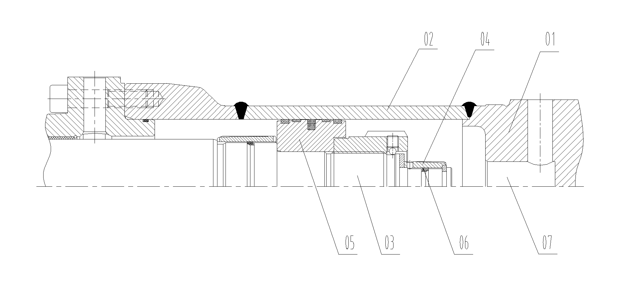
Therefore in the above hydraulic oil cylinder, failures of the buffer mechanism that the buffer sleeve 04 fails to insert into the buffer inner hole 07 are very easy to happen, which may cause the entire hydraulic oil cylinder being not able to operate normally.
Another key problem of the above buffer mechanism is that, the outer diameter of the small buffer sleeve 04 must fit with the inner diameter of the buffer inner hole 07 precisely, otherwise the buffer effect may not be achieved, thus the buffer mechanism has an extremely high manufacturing precision requirement which is hard to meet for manufacturers with ordinary manufacturing level.
Due to the excessive high manufacturing precision requirements, the hydraulic oil cylinder with a large cylinder diameter and a long stroke has become a bottleneck problem for producing construction machineries such as excavators, which severely restricts the production capacity of the manufacturers in downstream production chain.

Method used


Image

  • Hydraulic Oil Cylinder and Related Equipments, Hydraulic Buffer System, Excavator and Concrete Pump Truck
  • Hydraulic Oil Cylinder and Related Equipments, Hydraulic Buffer System, Excavator and Concrete Pump Truck
  • Hydraulic Oil Cylinder and Related Equipments, Hydraulic Buffer System, Excavator and Concrete Pump Truck

Examples


Embodiment Construction

[0057]The first embodiment of the present application provides a hydraulic oil cylinder with a buffer device provided in a rodless cavity side of the hydraulic oil cylinder.

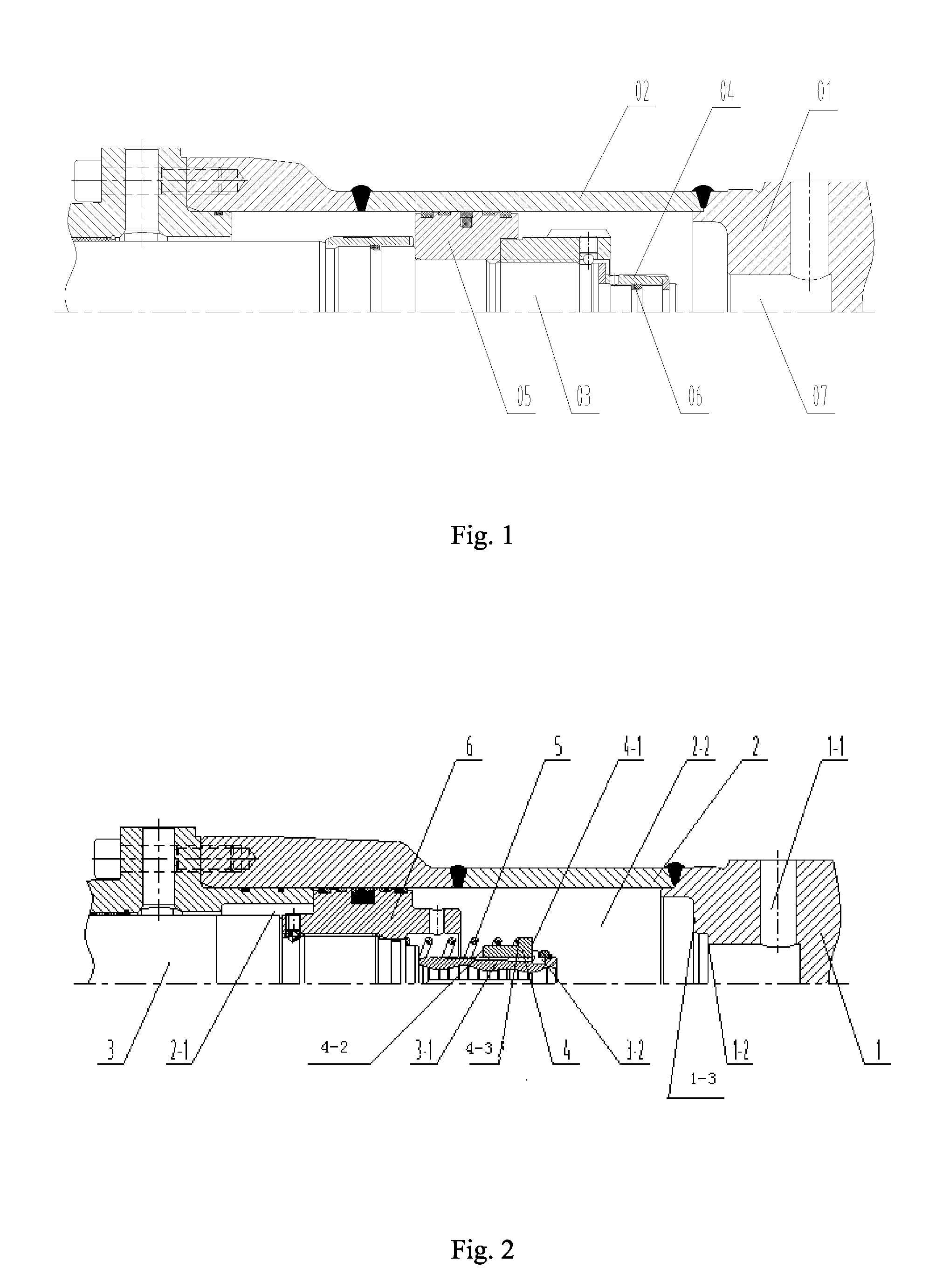
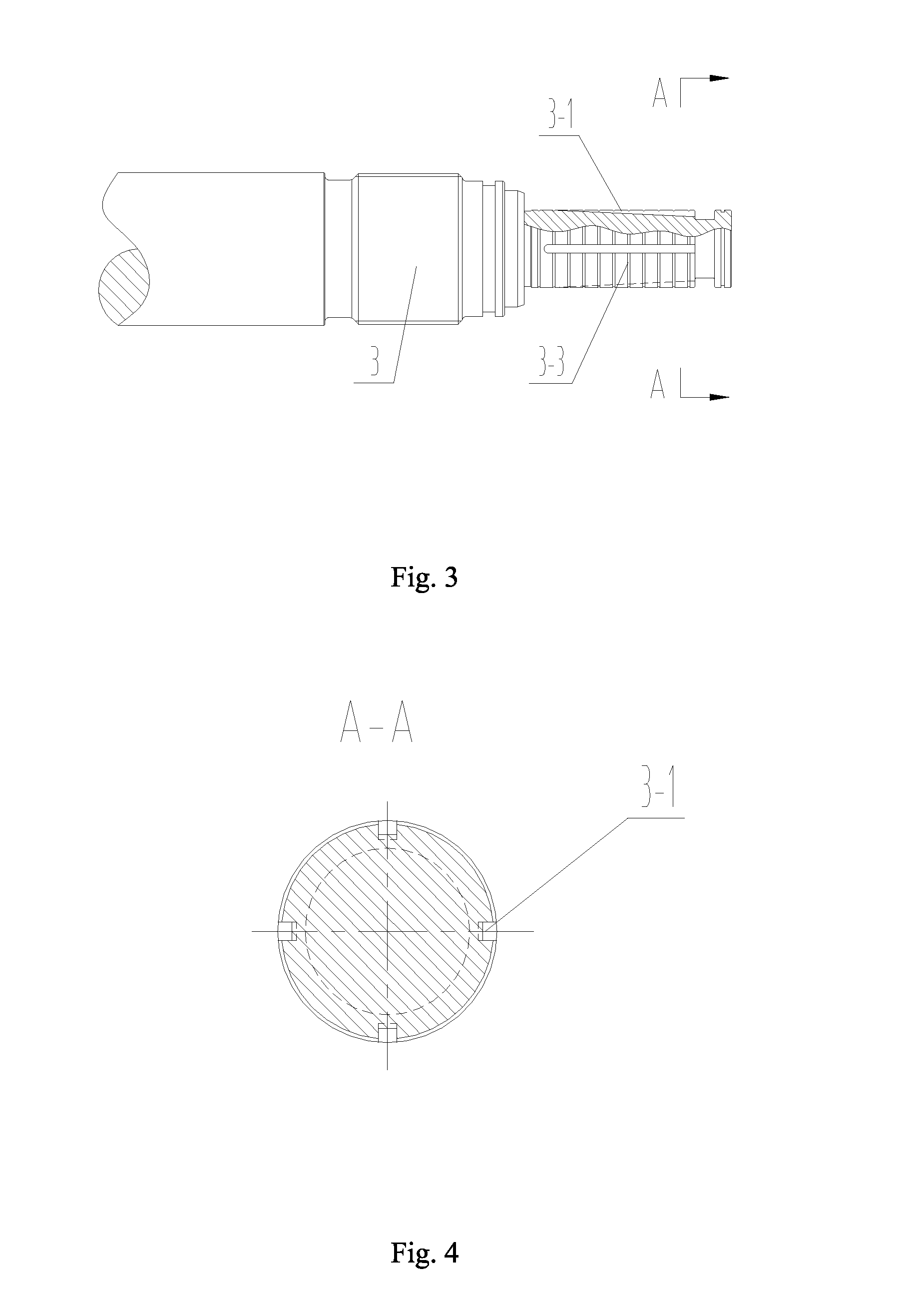
[0058]Referring to FIG. 2, FIG. 2 is a mechanical structural view of the hydraulic oil cylinder according to the first embodiment of the present application, wherein the piston has not yet retracted to the buffer position in the rodless cavity.

[0059]As shown in FIG. 2, the hydraulic oil cylinder includes a rodless cavity end cover 1, a cylinder barrel 2, a piston rod 3, a buffer sleeve 4, a spring 5 and a piston 6.

[0060]The cylinder barrel 2 provides a space for sealing the hydraulic oil to the hydraulic oil cylinder, an inner cavity of the cylinder barrel 2 is divided into a rod cavity 2-1 and a rodless cavity 2-2 by the piston 6 which is movable axially along a cavity body of the inner cavity, and a cavity body at which a main body of the piston rod 3 is located is the rod cavity 2-1. An outer diameter surface ...


PUM


Abstract

A hydraulic oil cylinder has a buffer sleeve (4), a rodless cavity sealing end face (1-2) and at least one throttle oil channel (3-1). The buffer sleeve (4) is sleeved on an additional section (3a) of a piston rod in the rodless cavity (2-2) and axially slidable along the additional section (3a) of the piston rod. The rodless cavity sealing end face (1-2) is provided in an oil cylinder cavity between a rodless cavity oil passing hole (1-1) and the termination of the rodless cavity end face of the piston for the retraction process of the piston rod (3), and enables to block the buffer sleeve (4) and attach to the first end surface (4-1) of the buffer sleeve thereby forming a sealing surface.

Description

[0001]The present application claims the benefit of priority to Chinese Patent Application No. 201010235136.2, titled “HYDRAULIC OIL CYLINDER AND RELATED EQUIPMENTS, HYDRAULIC BUFFER SYSTEM, EXCAVATOR AND CONCRETE PUMP TRUCK”, filed with the Chinese State Intellectual Property Office on Jul. 23, 2010, the entire disclosure of which is incorporated herein by reference.FIELD OF THE INVENTION[0002]The present application relates to the field of hydraulic technology, and particularly to a hydraulic oil cylinder. The present application also provides related devices for the hydraulic oil cylinder, and a hydraulic buffer system having the hydraulic oil cylinder, an excavator and a concrete pump truck both having the hydraulic oil cylinder.BACKGROUND OF THE INVENTION[0003]The hydraulic oil cylinder is a component widely used in the construction machinery, and during the working process of the hydraulic oil cylinder a piston needs to reciprocate continuously. When a piston rod extends to a ...

Claims


Application Information

Patent Timeline
IPC IPC(8): F15B15/20
CPCF15B15/20F15B15/222
Inventor YI, XIAOGANGLIU, YONGDONGCHEN, BINGBING
Owner HUNAN SANY INTELLIGENT CONTROL EQUIP
Learn More