
Physiological measurement device or wearable device interface simulator and method of use

a technology of wearable devices and simulators, applied in medical science, prosthesis, diagnostics, etc., can solve the problems of uneven distribution, deleterious affect of subjects, and soft tissue tends to move, and achieve the effect of increasing accuracy

Inactive Publication Date: 2013-08-01
MASSACHUSETTS INST OF TECH
View PDF13 Cites 45 Cited by
  • Summary
  • Abstract
  • Description
  • Claims
  • Application Information

AI Technical Summary

Benefits of technology

The invention allows for more accurate modeling and measurement of physiological features on a subject and increases the accuracy of simulations of interactions between a wearable device and the subject. This is achieved by fixing the position of at least a portion of the surfaces, regardless of the forces applied.

Problems solved by technology

Body-attachable devices employed to support a subject at, for example, a limb or the terminal end of a residual limb, often cause significant problems consequent to uneven distribution of force at surface areas of the subject in contact with the supporting orthosis or prosthesis.
Although orthoses and prostheses typically are fitted by forming a material to the contours of the area of contact with the subject, soft tissue tends to move under use conditions consequent to linear and non-linear changes and differences in load, impedance and stiffness across the interface between the orthosis or prosthesis and the subject.
Such changes of the soft tissue underlying the interface redistributes force across the area of the orthosis or prosthesis contacting the subject and can, as a consequence, deleteriously affect the subject not only in the area of contact with the prosthesis but, secondarily, as a result of efforts by the subject to minimize discomfort caused by that uneven distribution of force during activity.
However, such attempts generally do not account for differences in load, impedance or stiffness across the interface between an orthosis or prosthesis and a subject and, therefore, cannot be manipulated to correct the types of forces distributed across the interface.

Method used


Image

  • Physiological measurement device or wearable device interface simulator and method of use
  • Physiological measurement device or wearable device interface simulator and method of use
  • Physiological measurement device or wearable device interface simulator and method of use

Examples


Embodiment Construction

[0022]A description of example embodiments of the invention follows. The invention generally is directed to a physiological measurement device or wearable device interface simulator. The invention is also directed generally to a method for measuring a physiological feature of a subject or simulating an interface of a wearable device.

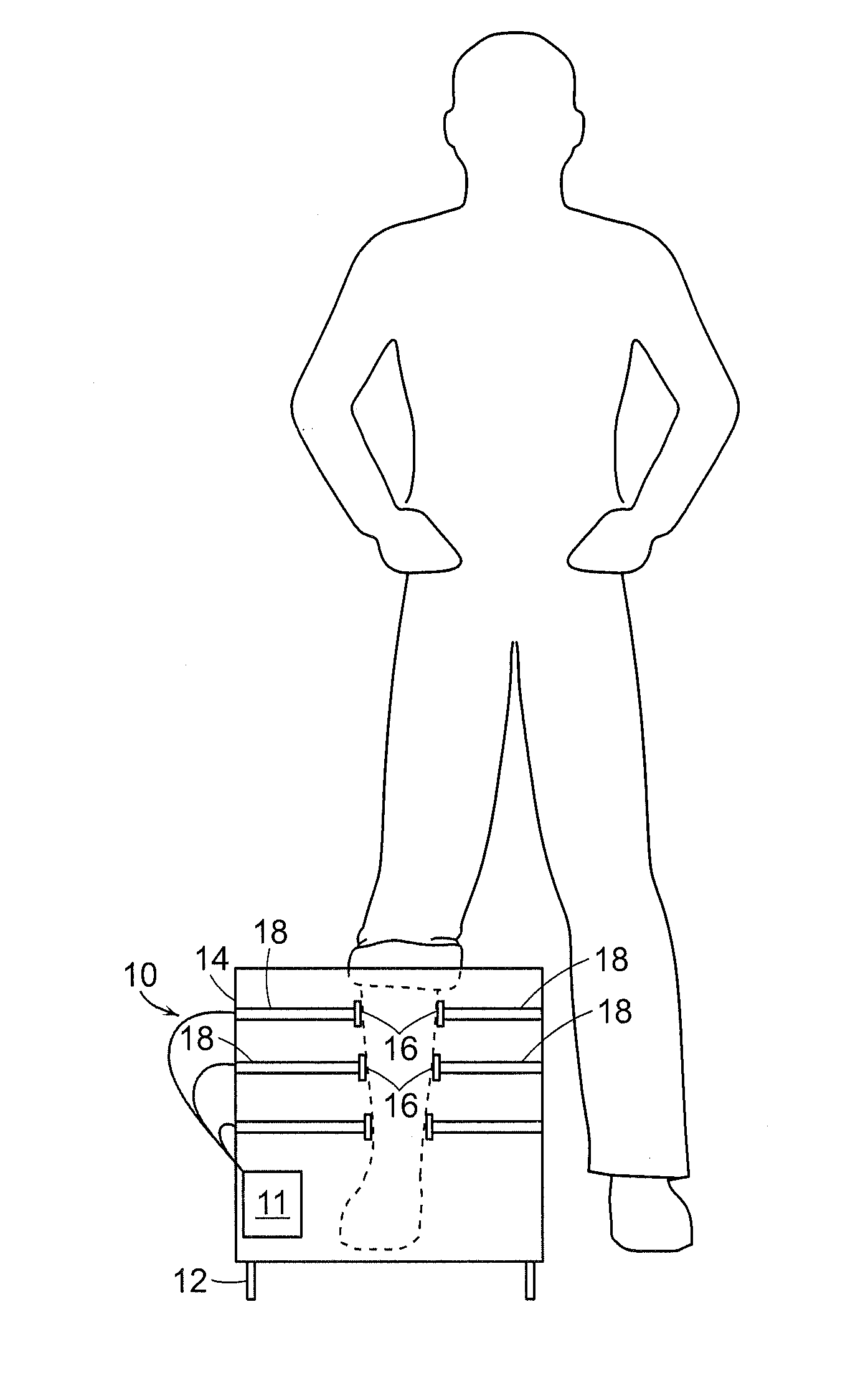
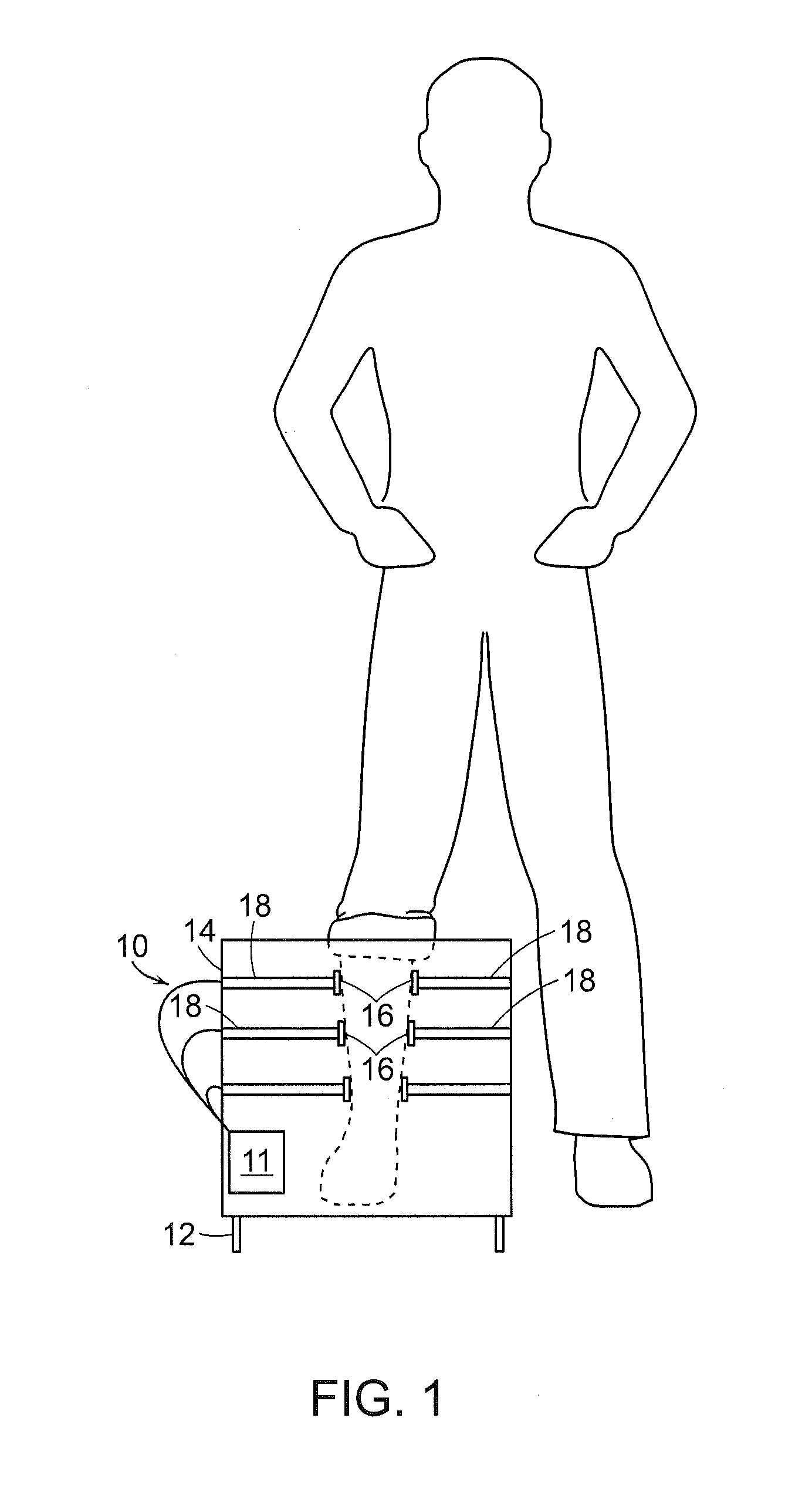
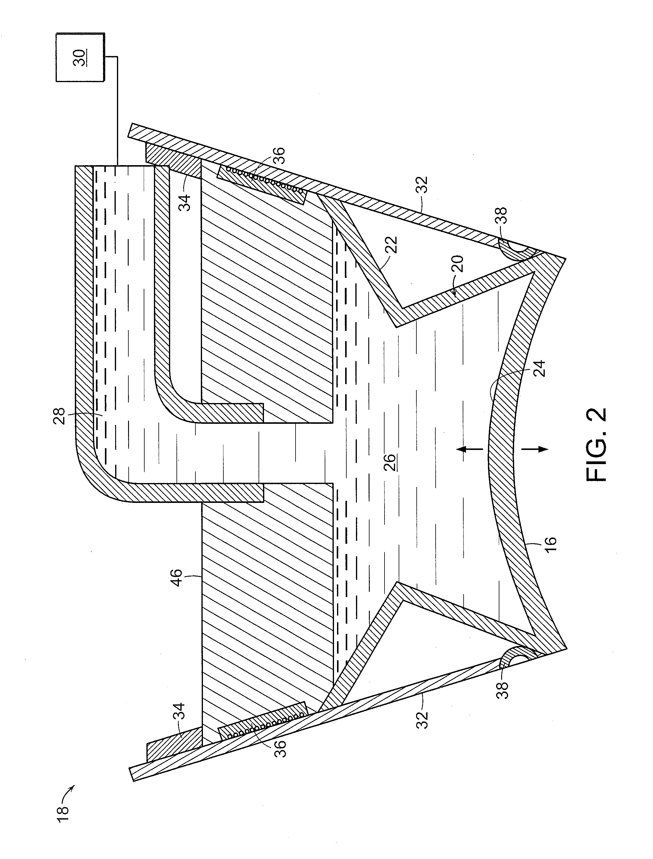
[0023]In one embodiment of the invention, shown in FIG. 1, physiological measurement device or wearable device interface simulator 10 includes support component 12 that fixes frame 14 relative to any or all of: i) a fixed point in space; ii) a skeletal feature of a subject proximate to a surface of the subject to be simulated or measured, and iii) the surface of the subject to be simulated or measured. Typically, support component will include rods and straps, as necessary, to minimize relative movement between frame and the physiological feature of the subject to be simulated or measured. A plurality of surfaces 16 are distributed within frame 14. Surfa...


PUM


Abstract

A physiological measurement device or wearable device simulator includes a frame and a plurality of surfaces distributed within the frame. For each surface, a surface actuator links the surface of the frame. At least one of: i) force or position imparted by the surface on a physiological feature of a subject by the surface actuator; and ii) the force imparted by the physiological feature of the subject on the surface, can be employed to modulate the positions of the surfaces relative to each other independently of the forces imparted by or on those surfaces, thereby measuring the physiological feature of the subject or simulating a wearable device interface.

Description

RELATED APPLICATION(S)[0001]This application claims the benefit of U.S. Provisional Application No. 61 / 576,275, filed on Dec. 15, 2011.[0002]The entire teachings of the above application are incorporated herein by reference.GOVERNMENT SUPPORT[0003]This invention was made with government support under VA118-12-C-0040 from United States Department of Veterans Affairs. The government has certain rights in the invention.BACKGROUND OF THE INVENTION[0004]Body-attachable devices employed to support a subject at, for example, a limb or the terminal end of a residual limb, often cause significant problems consequent to uneven distribution of force at surface areas of the subject in contact with the supporting orthosis or prosthesis. Although orthoses and prostheses typically are fitted by forming a material to the contours of the area of contact with the subject, soft tissue tends to move under use conditions consequent to linear and non-linear changes and differences in load, impedance and ...

Claims


Application Information

Patent Timeline
IPC IPC(8): A61B5/00A61B5/01A61B5/11A61B5/107
CPCA61B5/4851A61B5/107A61B5/01A61B5/11A61B5/4848A61F2002/762A61B2562/0247A61B2562/046A61F2/76A61F2002/5049A61B5/1077
Inventor HERR, HUGH M.PETRON, ARTHUR
Owner MASSACHUSETTS INST OF TECH
Learn More