Manufacturing method for coil unit

a manufacturing method and coil technology, applied in the direction of windings conductor shape/form/construction, dynamo-electric machines, electrical apparatus, etc., can solve the problems of increasing the space factor of the coil, and increasing the length of the winding process. , to achieve the effect of reducing the radial width of the coil conductor wire, and enhancing the space factor

Inactive Publication Date: 2013-08-01
AISIN AW CO LTD
View PDF0 Cites 9 Cited by
  • Summary
  • Abstract
  • Description
  • Claims
  • Application Information

AI Technical Summary

Benefits of technology

[0011]According to the manufacturing method, the coil conductor wire, the diameter of which is larger than the slot opening width in the case where the cross-sectional shape of the coil conductor wire is circular, is inserted into the slot, from the slot opening portion with the circumferential wire width of the toil Conductor wire equal to or less than the slot opening width. Thus, a conductor wire with a large wire diameter can be used as the coil conductor wire. In addition, the number of conductor wires in the slot is reduced, thereby decreasing the amount of insulating covering in the slot to enhance the space factor of the conductor wires. Further, the possibility of a wire breakage and an increase in number of turns of the conductor wires to be wound around the core are suppressed. That is, according to the above-described configuration, it is possible to form a stator or a rotor of a rotary electric machine by forming a coil unit by winding the coil conductor wire with a high space factor around the core having the plurality of slots disposed in a distributed manner in the circumferential direction of the cylindrical core reference surface.
[0013]Here, in one aspect, the pressing step of the manufacturing method for a coil unit according to the present invention may include deforming the cross-sectional shape of the coil conductor wire such that the circumferential wire width becomes larger than the circumferential wire width at a tune of insertion into the slot opening portion in the insertion step. According to the aspect, the cross-sectional shape of the coil conductor wire is deformed such that the circumferential wire width becomes larger than that at a time of insertion into the slot opening portion. That is, the coil conductor wire is widened in the circumferential direction inside the slot, thereby reducing the gap between an inner wall of the slot and the coil conductor wire to enhance the space factor. In addition, with the circumferential wire width of the coil conductor wire widened, the radial wire width of the coil conductor wire is reduced. This accordingly allows insertion of the coil conductor wires into the slot, thereby enhancing the space factor.
[0014]Examples of the shape of the slot include a so-called semi-open slot in which the slot opening width is narrower than the circumferential width of the internal space of the slot. In the case of a semi-open slot, if the coil conductor wire is pressed such that the circumferential wire width of the coil conductor wire inserted into the internal space of the slot is larger than the slot opening width, the space factor of the coil conductor wires in the slot can be enhanced. That is, in one aspect of the manufacturing method for a coil unit according to the present invention, in the case where the slot has an internal space that is wider in the circumferential direction on a side in the depth direction with respect to the slot opening portion than at the slot opening portion, the pressing step may include deforming the cross-sectional shape of the coil conductor wire such that the circumferential wire width of the coil conductor wire is larger than the slot opening width.
[0015]The slot opening width is smaller than the diameter of the coil conductor wire with a circular cross-sectional shape. In the case of a semi-open slot in which the slot opening width is narrower than the circumferential width of the internal space of the slot, the coil conductor wire may be pressed such that the circumferential width of the coil conductor wire inserted into the internal space of the slot becomes larger than the diameter of the coil conductor wire with a circular cross-sectional shape to enhance the space factor. That is, in one aspect of the manufacturing method for a coil unit according to the present invention, in the case where the slot has an internal space that is wider in the circumferential direction on a side in the depth direction with respect to the slot opening portion than at the slot opening portion, the pressing step may include deforming the cross-sectional shape of the coil conductor wire such that the circumferential wire width in the slot is larger than the diameter of the coil conductor wire with a circular cross-sectional shape.
[0017]Further, the coil conductor wire with a flexible insulating covering material may have an in-covering gap provided radially inwardly of the insulating covering material to make the conductor element wires movable relative to each other. With the insulating covering material flexible and with the in-covering gap provided radially inwardly of the insulating covering material, the conductor element wires are movable relative to each other in the in-covering gap. Thus, the shape of the conductor wire in cross section taken in the orthogonal extending plane can be deformed relatively freely even in the case where the insulating covering material is not highly elastic. Therefore, the manufacturing method for a coil unit according to the aspect of the present invention is suitable for the properties of the coil conductor wire.

Problems solved by technology

With a conductor wire with a circular cross section, however, gaps tend to be formed between conductor wires in the slots in attaching the conductor wires to the stator, which makes it difficult to enhance the space factor of the coils.
In the case where the diameter of the conductor wires is reduced, however, it may be necessary to make contrivances not to cause a wire breakage in winding the conductor wires around the core, or the number of turns of the conductor wires to be wound around the core may be increased, which may require longer time for a winding process.
In this case, however, the shape of the slots is also limited to a shape corresponding to the cross-sectional shape of the conductor wire, and the slots or teeth may not necessarily have an optimum shape.
Therefore, a single conductor wire may not be wound continuously.
This may raise the need to weld divided conductor wires to each other at a plurality of points, which may increase the number of man-hours, increase a loss due to such welding, and impede a reduction in size of a rotary electric machine in the case where there are a large number of such welding points.
In addition, while the technology according to JP 2011-91943 A can be applied to the split core, it is difficult to apply the technology according to JP 2011-91943 A to an integrated core formed in a cylindrical shape, for example.

Method used


Image

  • Manufacturing method for coil unit
  • Manufacturing method for coil unit
  • Manufacturing method for coil unit

Examples


Embodiment Construction

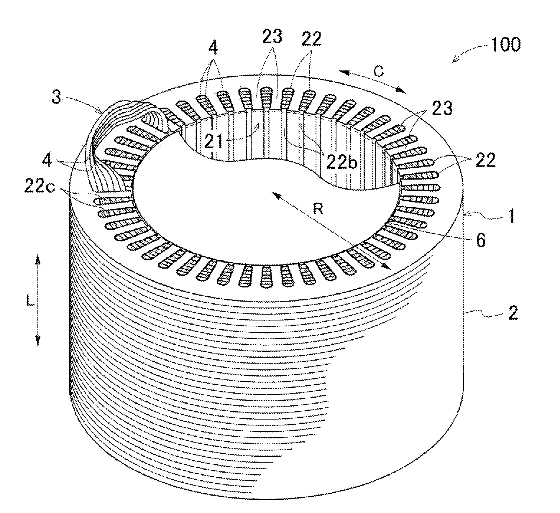
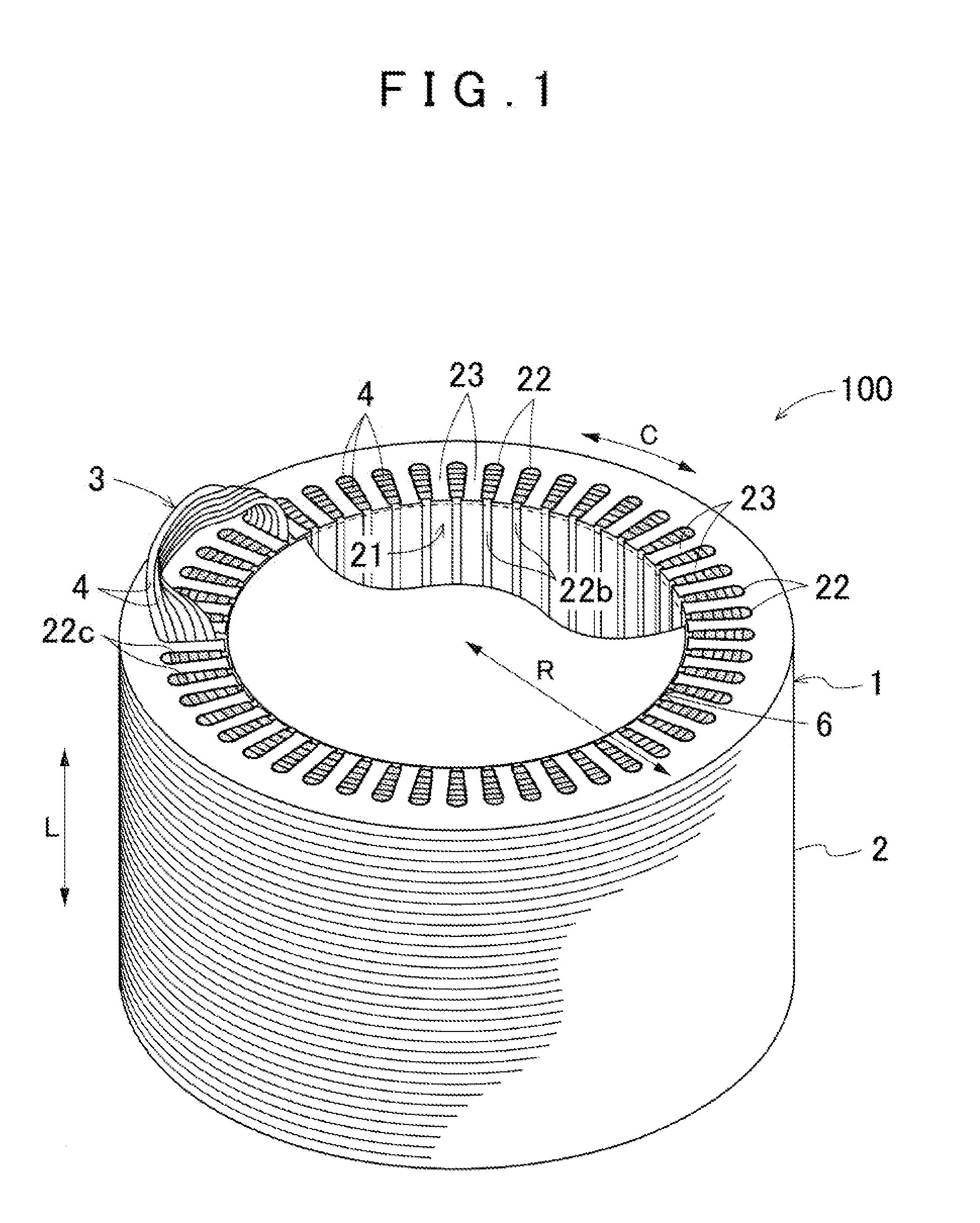
[0035]An embodiment of the present invention will be described below with reference to the drawings. Here, the present invention is described as being applied to a rotary electric machine 100 of an inner rotor type as shown in FIG. 1. Unless otherwise noted, the terms “axial direction L”, “circumferential direction C”, and “radial direction R” as used herein are defined with reference to the axis of a cylindrical core reference surface 21 of a stator core 2 to be described later (for example, the inner circumferential surface of the stator core 2) (see FIG. 1).

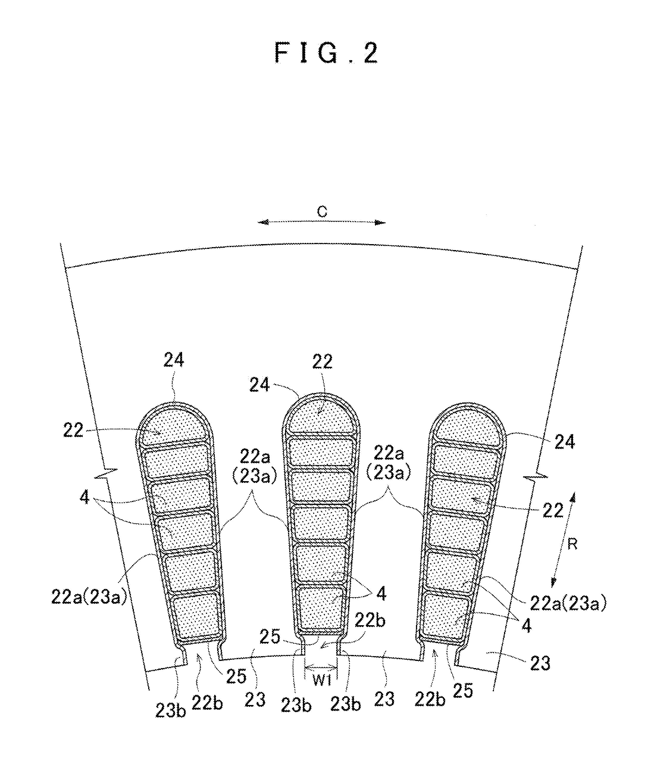
[0036]A conductor wire 4 (coil conductor wire) that forms a coil 3 (stator coil) in a stator 1 of the rotary electric machine 100 has a deformable cross-sectional shape. In the present embodiment, as shown in FIG. 3, the conductor wire 4 includes a conductor element wire bundle 42 formed by gathering a plurality of conductor element wires 41, and a flexible insulating covering material 46 that covers the periphery of the condu...


PUM

PropertyMeasurementUnit
diameteraaaaaaaaaa
widthaaaaaaaaaa
diameteraaaaaaaaaa

Abstract

A method for manufacturing a coil unit includes inserting a coil conductor wire into a slot from a slot opening portion with a circumferential wire width of the coil conductor wire equal to or less than a slot opening width, the slot opening width being a width of the slot opening portion in the circumferential direction, the circumferential wire width being a wire width of the coil conductor wire in a direction parallel with the slot opening width, the coil conductor wire being a conductor wire with a deformable cross-sectional shape, and a diameter of the coil conductor wire with a circular cross-sectional shape being larger than the slot opening width; and pressing the coil conductor wire inserted into the slot in a depth direction which is opposite to the opening direction to deform the cross-sectional shape of the coil conductor wire.

Description

INCORPORATION BY REFERENCE[0001]The disclosure of Japanese Patent Application No. 2012-018990 filed on Jan. 31, 2012 including the specification, drawings and abstract is incorporated herein by reference in its entirety.BACKGROUND OF THE INVENTION[0002]The present invention relates to a method for manufacturing a coil unit that forms a stator or a rotor of a rotary electric machine, in which a coil conductor wire is wound around a core having a plurality of slots disposed in a distributed manner in the circumferential direction of a cylindrical core reference surface.Description of the Related Art[0003]A stator or a rotor provided in a rotary electric machine serving as an electric motor or an electric generator to function as an armature is formed by attaching coils to a core (a stator core or a rotor core) having a plurality of slots. For example, a stator formed as an armature has coils, which are formed by winding a conductor wire with a circular cross section in a multiplicity ...

Claims


Application Information

Patent Timeline
Patent Type & Authority Applications(United States)
IPC IPC(8): H02K3/04
CPCH02K3/12H02K15/0031Y10T29/49009H02K3/04H02K15/085
Inventor KOGA, KIYOTAKA
Owner AISIN AW CO LTD
Why Eureka
Try Eureka