
Communications network

a communication network and network technology, applied in the field of communication networks, can solve the problems of no qos scheme implemented for the hop between cpe and the broadband remote access server, adversely affecting the user experience deriving from other applications using the same network connection, and even the user experience of users using other network connections

Active Publication Date: 2013-07-25
BRITISH TELECOMM PLC
View PDF17 Cites 14 Cited by
  • Summary
  • Abstract
  • Description
  • Claims
  • Application Information

AI Technical Summary

Benefits of technology

The invention provides an arrangement for marking traffic in a packet-switched data network to indicate its quality of service level. This helps to ensure that the network can deliver information to its users in a timely and reliable manner. The invention involves a network element that stores marking rules, which indicate the level of service allocated to a connection that impinges on the network element. The network element detects new connections and derives quality of service level data for them based on information from a distributed hierarchical naming system. The network element can also allocate an initial quality of service level marking to new connections and cache locally data obtained from the distributed hierarchical naming system. Overall, the invention helps to ensure network resilience and improved user experience.

Problems solved by technology

Classifying traffic remains one of the hardest problems related to QoS in a modern network.
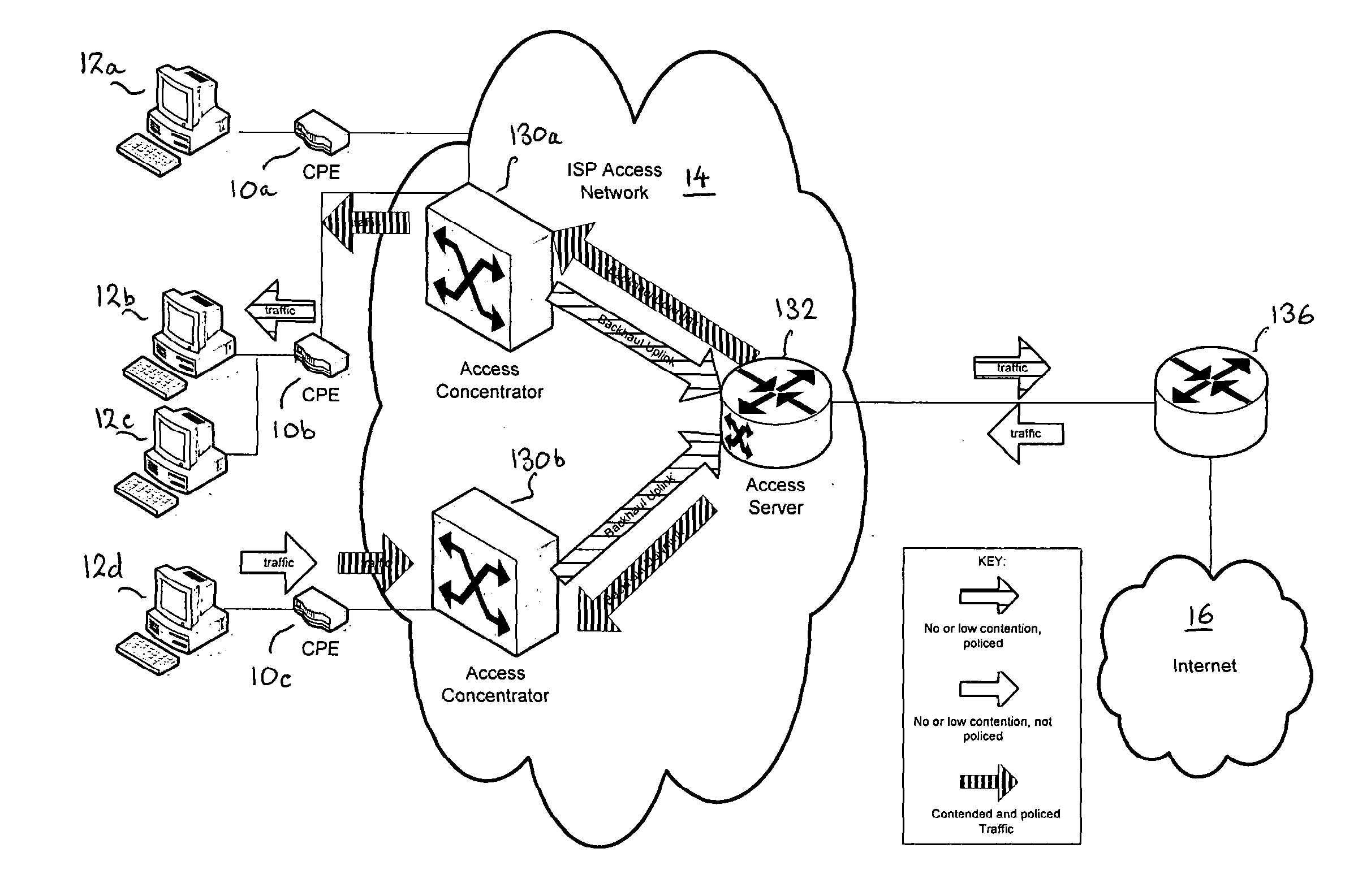
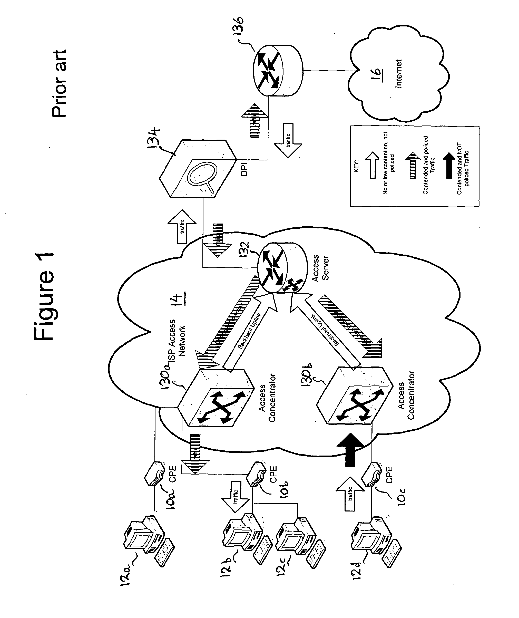
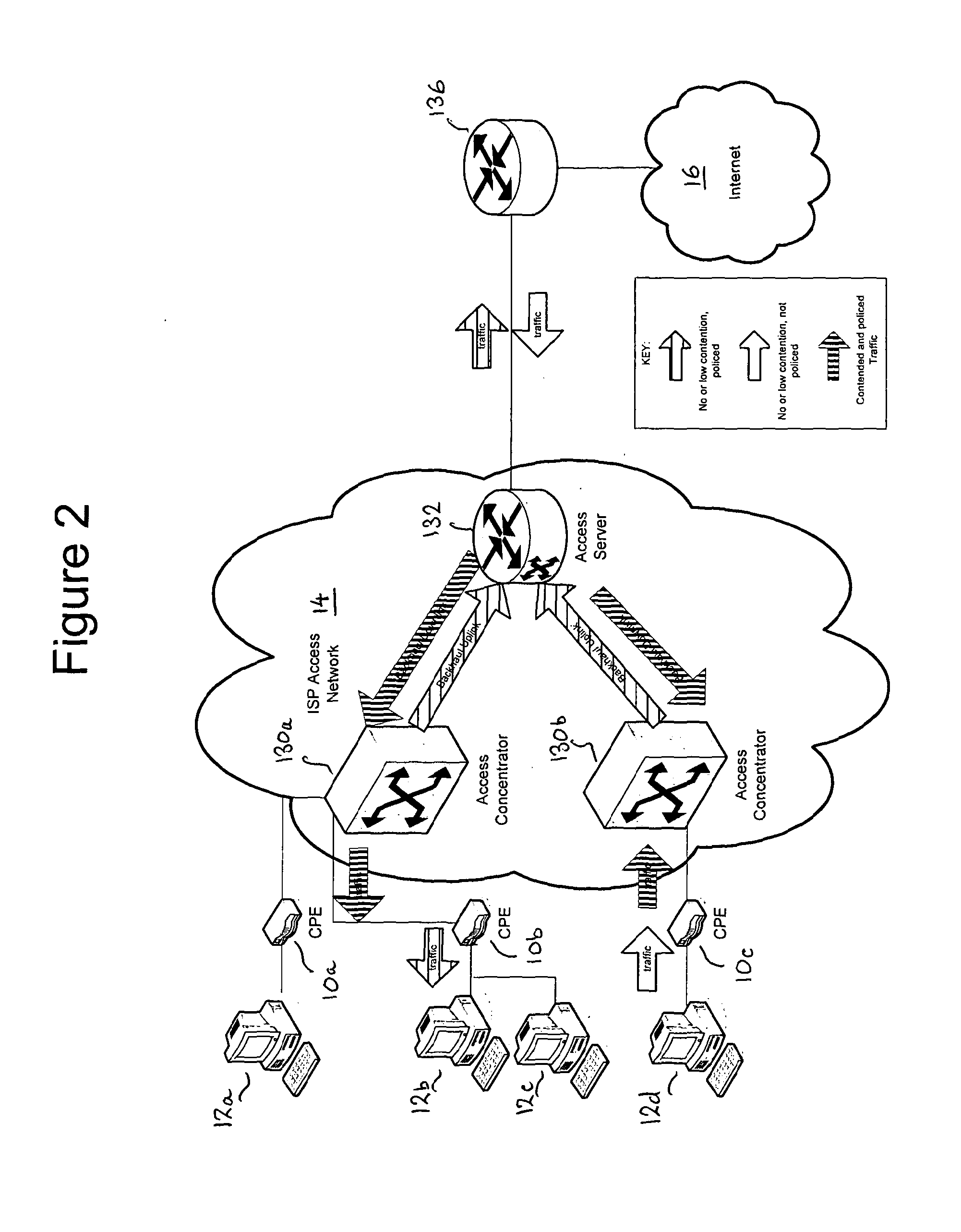
A problem with currently-deployed CPEs is that, in most modern broadband networks, CPE does not mark the traffic and, as a result, no QoS scheme is implemented for the hop between CPE and the Broadband Remote Access Server (BRAS).
As a result, there are multiple scenarios in which one application using a network connection could adversely affect the user experience deriving from other applications using the same network connection and even the user experience of users using other network connections.
This may involve a significant additional cost in terms of complexity, hardware and operational costs.
Between CPE 10c and access concentrator 130b, the unpoliced traffic experiences contention, thus raising the possibility that the service levels achieved will not be sufficient to provide an adequate user experience.

Method used


Image

  • Communications network
  • Communications network
  • Communications network

Examples


Embodiment Construction

[0029]The invention will now be described by way of example with reference to a CPE, although it will be understood that the invention is not limited to use with CPE but may operate with any form of network switching, routing or similar equipment that has access to DNS or similar distributed hierarchical naming system. The invention provides an efficient way of obtaining and using at a network element, data specifying a quality of service level for traffic impinging on the network element. We use the term “impinging” to indicate traffic arriving at or leaving the network element. The traffic may be on a connection originating or terminating at the network element or passing through it. The invention is particularly useful when applied to a CPE, which conventionally has no mechanism for marking traffic in this way.

[0030]The invention provides a method for configuring a network element (e.g. CPE, router, switch, or similar device) to classify traffic for QoS purposes. The network elem...


PUM


Abstract

A network element and method for marking traffic in a packet-switched data network which comprises a distributed hierarchical naming system and the network element. The network element comprises a marking rule store for storing marking rules, in which each marking rule is indicative of a quality of service level allocated to traffic on a connection impinging on the network element. The network element derives from the distributed hierarchical naming system quality of service level data for a connection, stores in the marking rule store a marking rule for the connection based on the retrieved quality of service level data and marks traffic on the connection in accordance with the marking rule.

Description

[0001]The invention is directed to communication networks in general and to managing the quality of service levels (QoS) of network traffic that utilizes such networks.[0002]We use QoS or “quality of service level” to denote a predictable service level provided to traffic in a data network and measured in relation to such parameters as bandwidth, jitter and delay. In today's communication networks, most services such as voice, video, and data utilize an IP-based transport. Use of a packet-switched network such as an IP network, as opposed to a dedicated circuit-switched one, greatly reduces the cost to the operator while, at the same time, facilitating the provision of new and innovative services for the consumer. However, the use of a shared medium such as a packet-switched network brings with it the problem of managing the QoS for the different types of traffic sharing the network.TECHNICAL BACKGROUND[0003]QoS Control in a Packet Switched Network.[0004]One means to control QoS in ...

Claims


Application Information

Patent Timeline
Patent Type & Authority Applications(United States)
IPC IPC(8): H04L12/26
CPCH04L29/12066H04L29/12783H04L47/10H04L43/0876H04L61/1511H04L61/35H04L47/2408H04L61/4511
Inventor IVANOV, ANTON RADOSTINOVINCHNADEAU, THOMAS DAVID
Owner BRITISH TELECOMM PLC
Learn More