
Drive assist system and drive assist method

a technology of driving assistance and auxiliary devices, which is applied in the direction of electric/magnetic computing, analogue processes for specific applications, instruments, etc., can solve the problems of low riding comfort or difficulty of drivers, poor driving skills may have difficulty in responding, and no appropriate drive assistance is provided

Inactive Publication Date: 2013-07-25
TOYOTA JIDOSHA KK
View PDF2 Cites 8 Cited by
  • Summary
  • Abstract
  • Description
  • Claims
  • Application Information

AI Technical Summary

Benefits of technology

The invention is a system and method for providing assistance to drivers by creating a personalized driving plan that takes into consideration the driver's preferences and abilities. The system analyzes data on how the driver uses the vehicle and adjusts the driving plan accordingly to ensure that the driver has a comfortable and safe ride. This helps to improve the driver's safety and ease of use. The system can also provide feedback on the driver's performance and suggest improvements to their driving habits. Overall, this invention helps to create a better driving experience for drivers and enhances the performance of vehicles.

Problems solved by technology

However, in the aforementioned related art, some drivers feel low riding comfort or difficulty in driving.
Further, there is also an apprehension that drivers with poor driving skills may have difficulty in making a response.
As a result, that is a possibility that appropriate drive assist is not provided.

Method used


Image

  • Drive assist system and drive assist method
  • Drive assist system and drive assist method
  • Drive assist system and drive assist method

Examples


Embodiment Construction

[0038]An embodiment of a drive assist system according to the invention will be described hereinafter in detail with reference to the drawings.

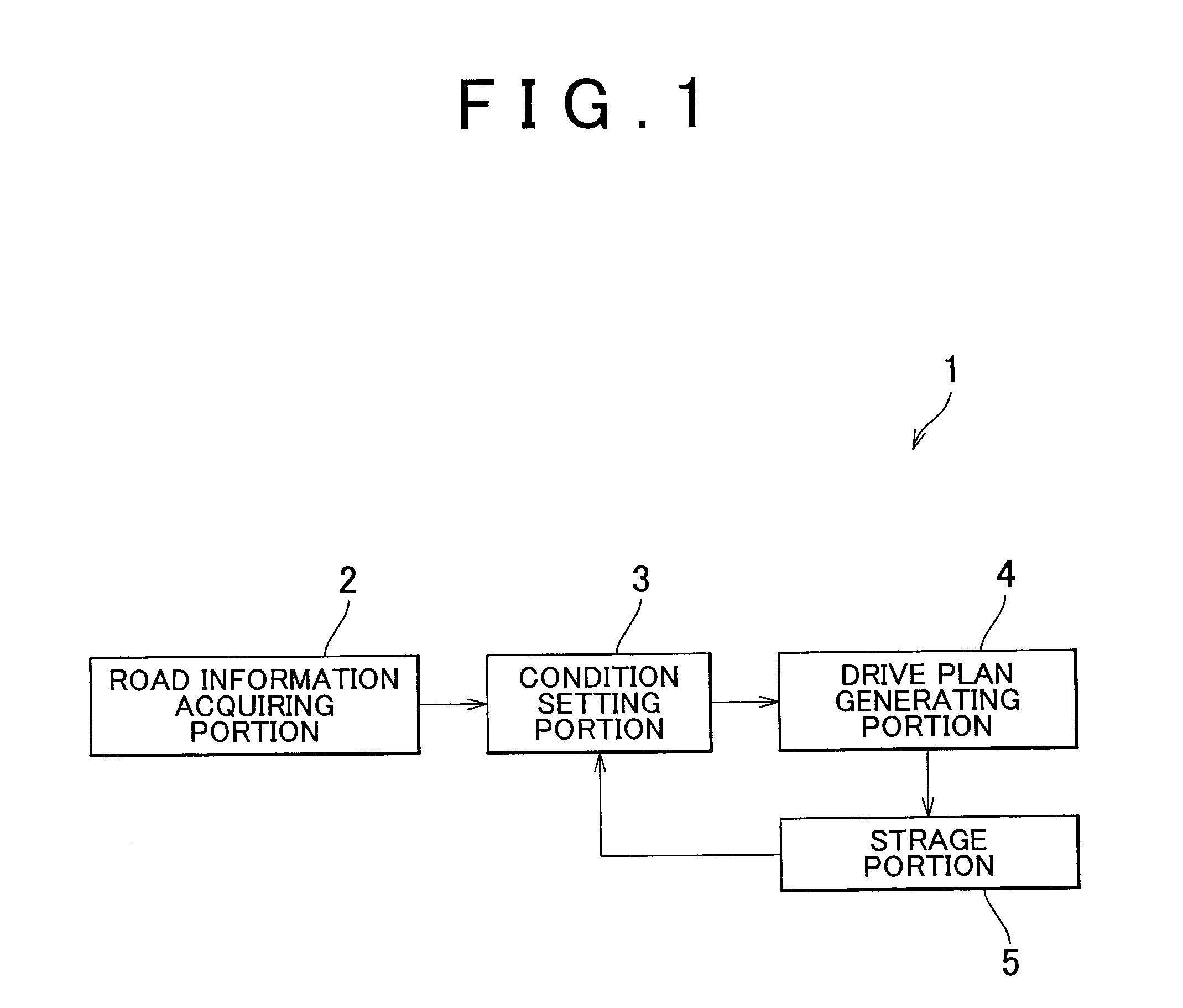
[0039]FIG. 1 is an overall configuration diagram showing one embodiment of a drive assist system according to the invention. In FIG. 1, a drive assist system 1 of this embodiment of the invention is a device that generates a drive plan (a locus) for a vehicle in an arbitrary section (a corner in this case) of a road on which the vehicle travels and provides support for the driving of the vehicle.

[0040]The drive assist system 1 has a road information acquiring portion 2, a condition setting portion 3, a drive plan generating portion 4, and a storage portion 5. The road information acquiring portion 2 acquires information on the shape and the like of a road on which the vehicle is about to travel. The road information acquiring portion 2 acquires, for example, information on navigation.

[0041]The condition setting portion 3 sets conditions neede...


PUM


Abstract

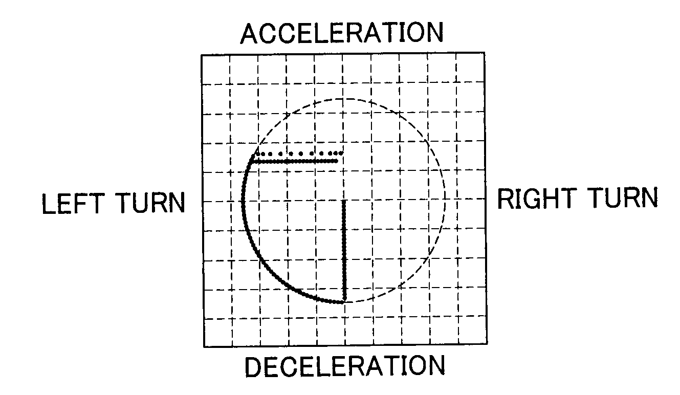
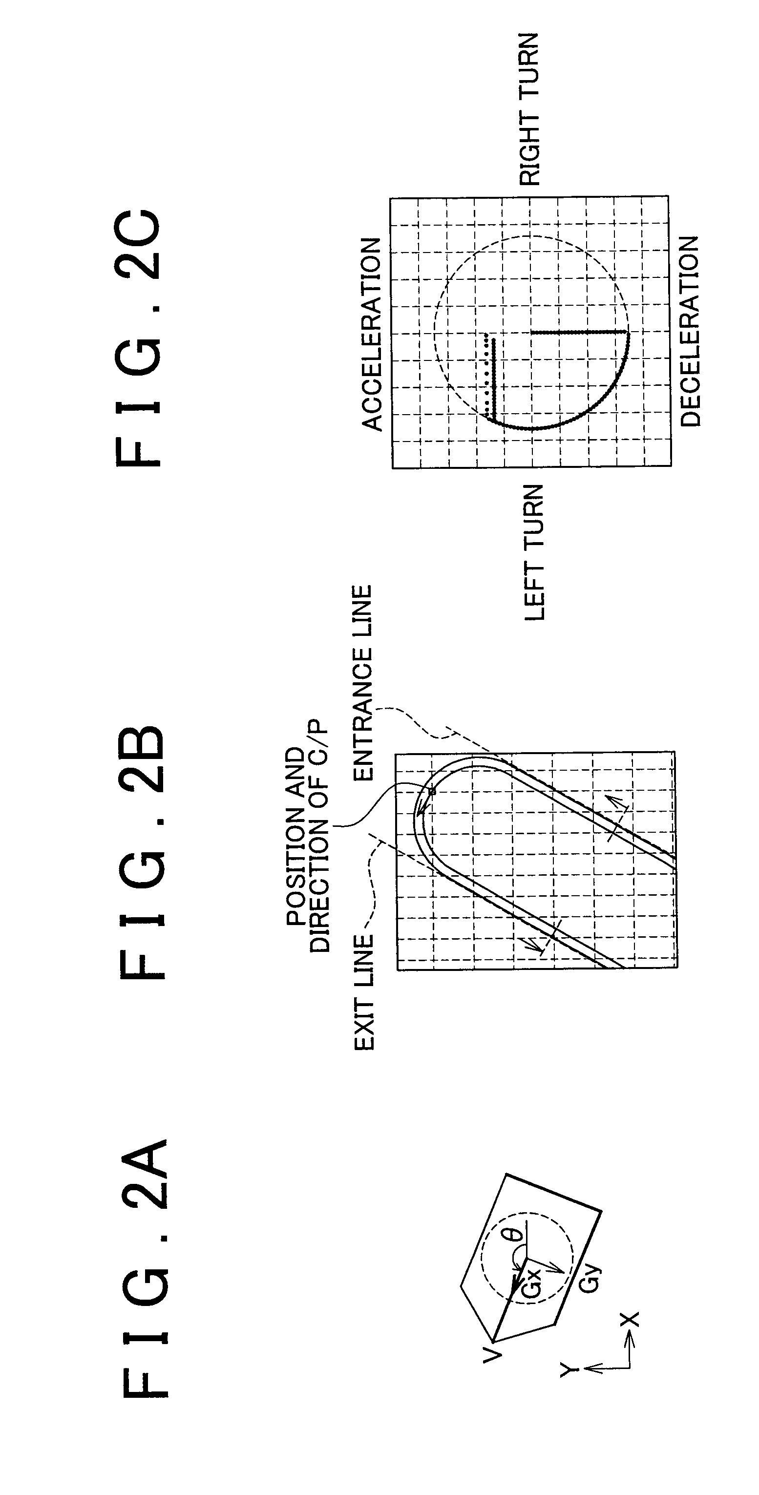
A drive assist system includes: an acceleration change pattern setting portion that sets an acceleration change pattern of a vehicle that is a pattern of change in acceleration of the vehicle that occurs while the vehicle travels on a road; and a drive plan generating portion that generates a drive plan for the vehicle based on the acceleration change pattern set by the acceleration change pattern setting portion. The drive assist system generates a drive plan satisfying three conditions, namely, a kinetic model of the vehicle, a passing point of each corner, and an acceleration change pattern, using a solution to two-point boundary-value problems.

Description

BACKGROUND OF THE INVENTION[0001]1. Field of the Invention[0002]The invention relates to a drive assist system and a drive assist method that assist a driver in driving a vehicle.[0003]2. Description of Related Art[0004]There is available a conventional drive assist system that generates, through the use of an optimization method, a drive plan for causing a vehicle to turn a corner fastest as described in Theoretical Studies on Minimum-time Cornering Method, Transactions of Society of Automotive Engineers of Japan, Vol. 23 No. 2, April 1992, for example.[0005]However, in the aforementioned related art, some drivers feel low riding comfort or difficulty in driving. Further, there is also an apprehension that drivers with poor driving skills may have difficulty in making a response. As a result, that is a possibility that appropriate drive assist is not provided.SUMMARY OF THE INVENTION[0006]The invention provides a drive assist system and a drive assist method that make it possible t...

Claims


Application Information

Patent Timeline
IPC IPC(8): G06F17/00
CPCB60W30/02B60W30/143B60W2520/125G06F17/00B60W2550/402B60W2720/106B60W2540/30B60W2556/50
Inventor MINASE, YUKINAKAI, KOJI
Owner TOYOTA JIDOSHA KK
Learn More