
Method for operating an accelerator pedal unit for motor vehicles

a technology for accelerator pedals and motor vehicles, which is applied in the direction of controlling members, limiting/preventing/returning parts, and sound producing devices. it can solve the problems of vehicle drivers being distracted from traffic, driver being supplied with a large amount of information, and unable to hear or ignore signals

Active Publication Date: 2013-07-25
CONTI TEMIC MICROELECTRONIC GMBH
View PDF1 Cites 12 Cited by
  • Summary
  • Abstract
  • Description
  • Claims
  • Application Information

AI Technical Summary

Benefits of technology

The technical improvement described in this patent makes it possible to create a consistent feeling of pressure on the driver's feet while driving.

Problems solved by technology

The technical problem addressed in this patent is how to provide efficient and effective communication between drivers and machines without causing them to become too distracted or unable to respond appropriately to important signals. Additionally, the patent addresses issues related to the use of torque motors in devices used for driving communications between drivers and machines.

Method used


Image

  • Method for operating an accelerator pedal unit for motor vehicles
  • Method for operating an accelerator pedal unit for motor vehicles
  • Method for operating an accelerator pedal unit for motor vehicles

Examples


Embodiment Construction

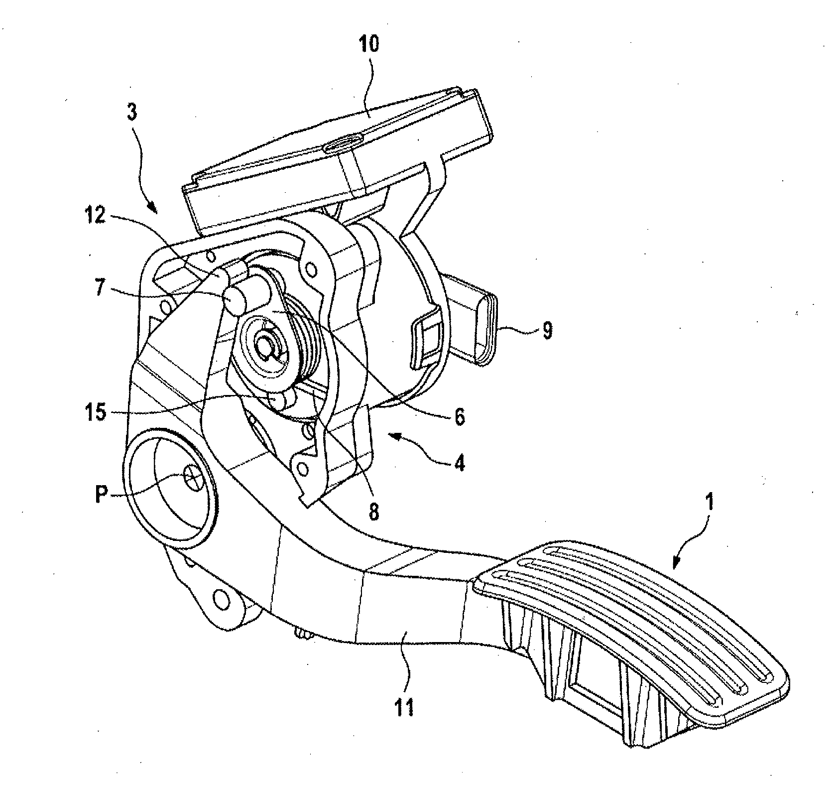
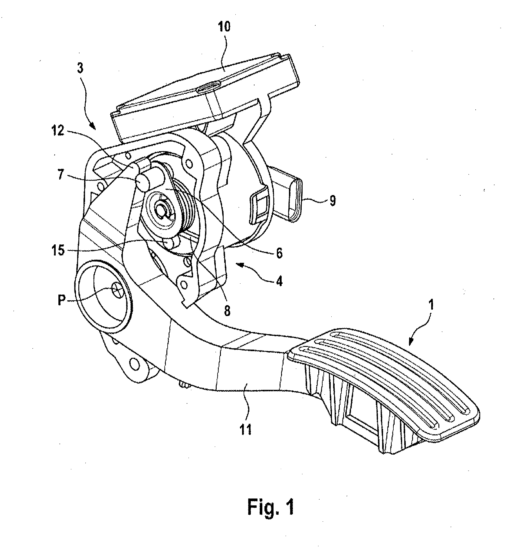
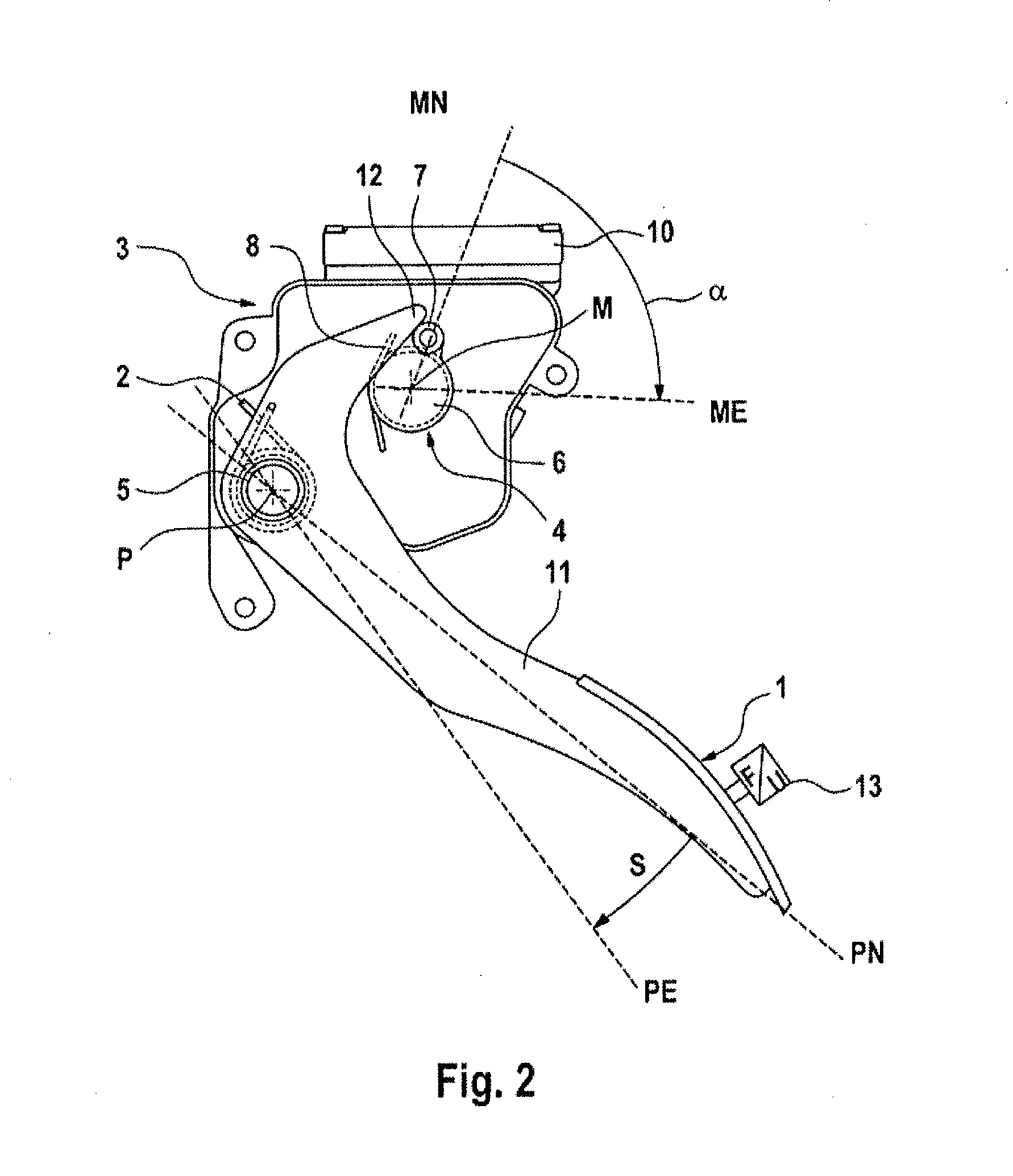
[0016]FIG. 1 illustrates an accelerator pedal unit for motor vehicles. If the vehicle driver steps on a pedal plate 1 of the accelerator pedal unit and a change in position of the pedal plate, brought about by the corresponding foot actuation force of said vehicle driver, of the pedal plate with respect to the starting position counter to a restoring force Fres occurs, this brings about an increase in the driving force of the drive motor of the motor vehicle. In this context, it is irrelevant whether the drive motor of the motor vehicle is implemented by an internal combustion engine or one or more electromotors or by a combination of the specified motors. If the vehicle driver releases his foot from the pedal plate 1, a restoring force Fres moves the pedal plate 1 back in the direction of its starting position. This restoring force is generated by a pedal restoring spring 2 (not illustrated in FIG. 1). The embodiment illustrated in FIG. 1 is also referred to as a hanging accelerato...


PUM


Abstract

A method for operating an accelerator pedal unit for motor vehicles, wherein a change in position of the pedal plate, which is brought about by a corresponding activation force, with respect to the starting position of said pedal plate counter to a restoring force of a pedal restoring spring brings about an increase in the driving force of the drive motor of the motor vehicle, and when the activation force diminishes the restoring force of the pedal restoring spring moves the pedal plate back in the direction of its starting position, wherein an electromechanical actuator which can be actuated externally is arranged in such a way that an additional restoring force acting on the pedal plate can be set.

Description


Claims


Application Information

Patent Timeline
Owner CONTI TEMIC MICROELECTRONIC GMBH
Learn More