Refrigerator
a technology of refrigerator and cooling fluid, which is applied in the direction of cooling fluid circulation, domestic cooling apparatus, lighting and heating apparatus, etc., can solve the problems of difficult to take efficient measures against cooling load, and achieve the effects of reducing the amount of refrigerant, improving energy efficiency, and saving energy
- Summary
- Abstract
- Description
- Claims
- Application Information
AI Technical Summary
Benefits of technology
Problems solved by technology
Method used
Image
Examples
first embodiment
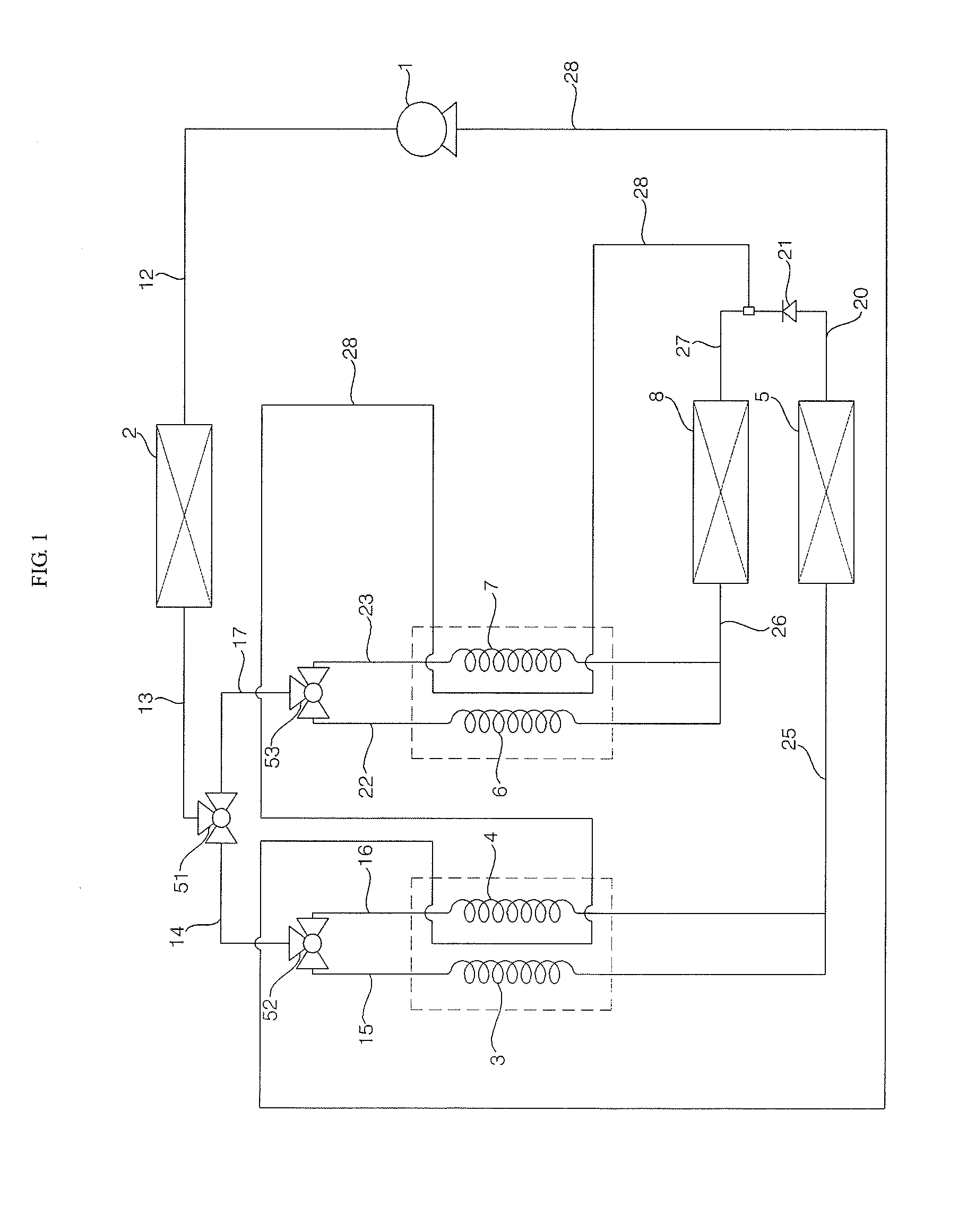
[0027]Referring to FIGS. 1 to 4, a refrigerator according to the present invention includes a compressor 1 that compresses a refrigerant, a condenser 2 that condenses the refrigerator compressed by the compressor 1, a first evaporator 5 and a second evaporator 8 that evaporate a refrigerant, a distributor 50 that distributes the refrigerant condensed by the condenser 2 to at least one of the first evaporator 5 and the second evaporator 8, a plurality of refrigerant channels 15 and 16 that is provided to supply the refrigerant distributed by the distributor 50 to the first evaporator 5, one or more second refrigerant channels 22 and 23 that are provided to supply the refrigerant distributed by the distributor 50 to the second evaporator 8, and a plurality of capillary tubes that is disposed in the first refrigerant channels and the second refrigerant channels, respectively.
[0028]The distributor 50 may include a first distributor 51 that distributes the refrigerant condensed by the co...
second embodiment
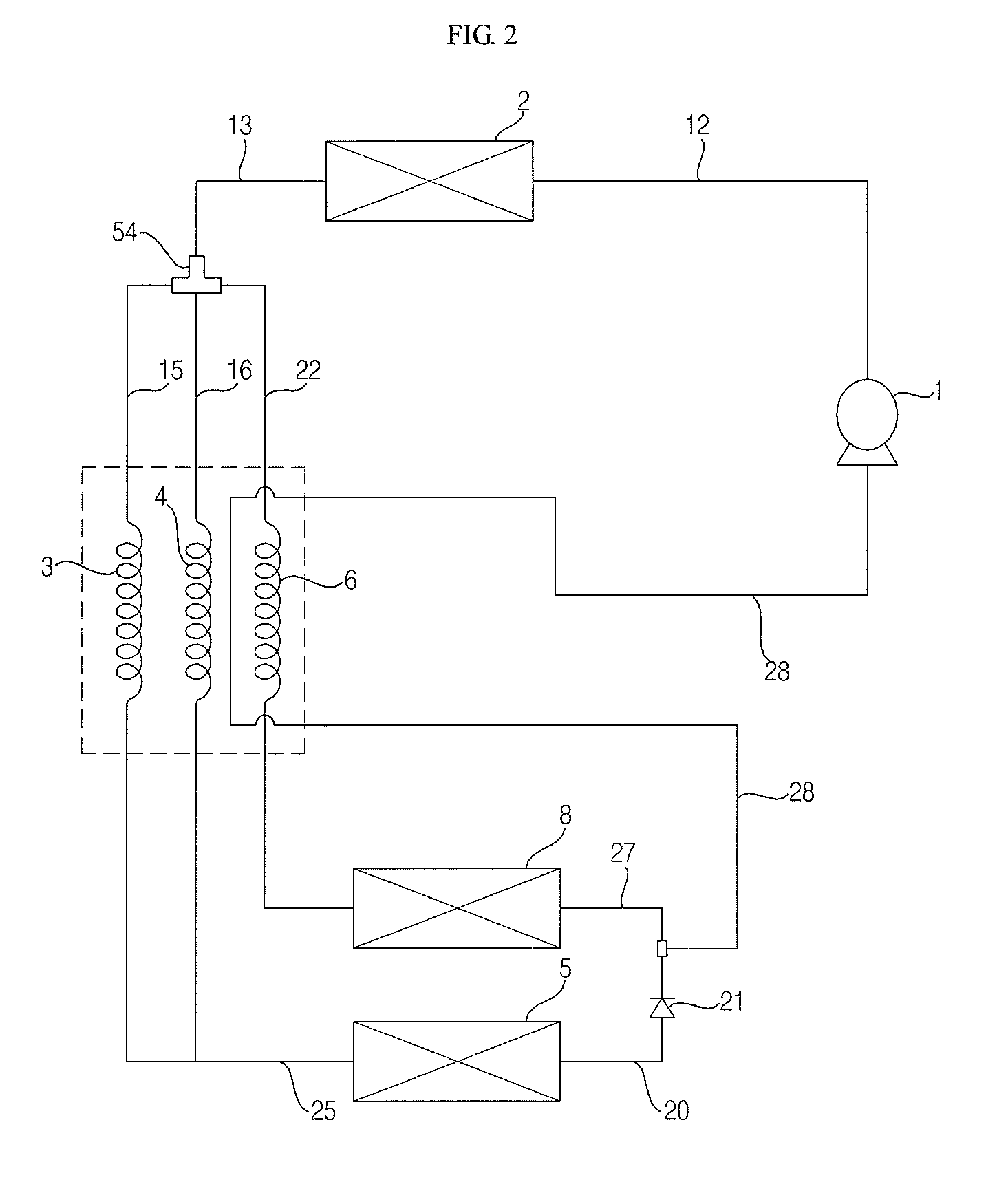
[0059]Referring to FIG. 2, a refrigerator according to the present invention includes a distributor 54 that selectively distributes a refrigerant condensed by a condenser 2 to a plurality of first refrigerant channels 15 and 16 and at least one second refrigerant channel 22. The distributor 54 can selectively distribute a refrigerant in accordance with cooling load. The distributor 54 may be connected with a discharged-from-condenser refrigerant channel 13 through which the refrigerant condensed by the condenser 2 is guided. The distributor 54 may be connected with the first refrigerant channels 15 and 16 or at least one second refrigerant channel 22.
[0060]The distributor 54 may include three or more refrigerant outlet connected with the first refrigerant channels 15 and 16 or the second refrigerant channel 22, and for example, it may be implemented by a 4-way valve. The 4-way valve means a valve with four ports herein. The first expansion refrigerant supply channel 15, the second e...
third embodiment
[0071]Referring to FIG. 3, a refrigerator according to the present invention includes a distributor 55 that distributes a refrigerant condensed by a condenser 2 to a plurality of refrigerant channels 15′ and 22′, capillary tubes 3′ and 6′ that are disposed in the refrigerant channels 15′ and 22′ and expand a refrigerant, and an evaporator 5′ that evaporates the refrigerant expanding through the capillary tubes 3′ and 6′.
[0072]Although it is exemplified that the distributor 55 distributes a refrigerant to a first refrigerant channel 15′ and a second refrigerant channel 22′ in the following description, the present invention is not limited thereto.
[0073]The distributor 55, a device that distributes the refrigerant condensed by the condenser 2 the first refrigerant channel 15′ and / or the second refrigerant channel 22′, may be implemented by a 3-way valve. The 3-way valve means a valve with three ports for a refrigerant herein. The distributor 55 can be controlled by appropriate control...
PUM
 Abstract
Description
Claims
Application Information
 - R&D
- Intellectual Property
- Life Sciences
- Materials
- Tech Scout
- Unparalleled Data Quality
- Higher Quality Content
- 60% Fewer Hallucinations
Browse by: Latest US Patents, China's latest patents, Technical Efficacy Thesaurus, Application Domain, Technology Topic, Popular Technical Reports.
© 2025 PatSnap. All rights reserved.Legal|Privacy policy|Modern Slavery Act Transparency Statement|Sitemap|About US| Contact US: help@patsnap.com


