
Mimicking Multi-Voltage Domain Wordline Decoding Logic for a Memory Array

a memory array and multi-voltage domain technology, applied in information storage, static storage, digital storage, etc., can solve the problems of large timing glitches, power consumption is a major issue, and device variations in the low voltage domain significantly influence the high voltage domain, and achieve the effect of stable relationship between the wordline and/or control signals of the memory array

Active Publication Date: 2013-07-18
QUALCOMM INC
View PDF4 Cites 13 Cited by
  • Summary
  • Abstract
  • Description
  • Claims
  • Application Information

AI Technical Summary

Benefits of technology

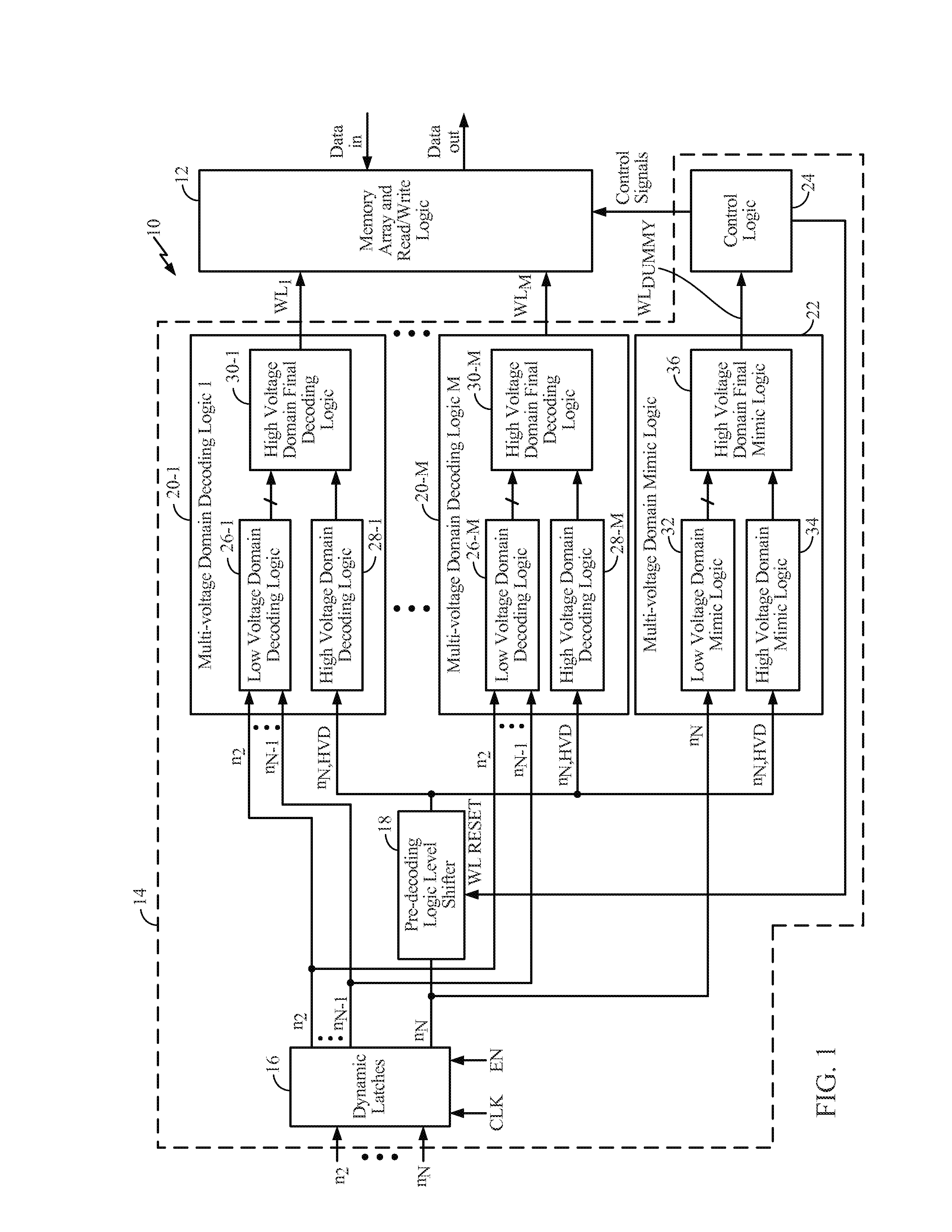
This patent describes a technology for improving the performance of a memory array. It includes a multi-voltage domain decoding logic that combines the outputs of low and high voltage logic to generate the wordline. Additionally, there is a multi-voltage domain mimic logic that mimics the decoding logic and generates a dummy wordline to maintain stable relationships between the wordline and control signals. The technical effect of this technology is improved performance and reliability of the memory array.

Problems solved by technology

Particularly for mobile devices, power consumption is a major issue.
One issue that arises in multi-voltage domain memory is that device variations in the low voltage domain significantly impact the high voltage domain.
More specifically, because devices typically operate much faster in the high voltage domain than in the low voltage domain, timing glitches that result from device variation in the low voltage domain translate to large timing glitches in the high voltage domain.
As a result of device variation and the corresponding timing glitch, control signals for multi-voltage domain memory (e.g., wordlines, pre-charge control signal, sense amplifier enable signal, etc.) may not maintain a stable relationship between one another, which in turn may cause the multi-voltage domain memory to fail.

Method used


Image

  • Mimicking Multi-Voltage Domain Wordline Decoding Logic for a Memory Array
  • Mimicking Multi-Voltage Domain Wordline Decoding Logic for a Memory Array
  • Mimicking Multi-Voltage Domain Wordline Decoding Logic for a Memory Array

Examples


Embodiment Construction

[0013]With reference now to the drawing figures, several exemplary embodiments of the present disclosure are described. The word “exemplary” is used herein to mean “serving as an example, instance, or illustration.” Any embodiment described herein as “exemplary” is not necessarily to be construed as preferred or advantageous over other embodiments.

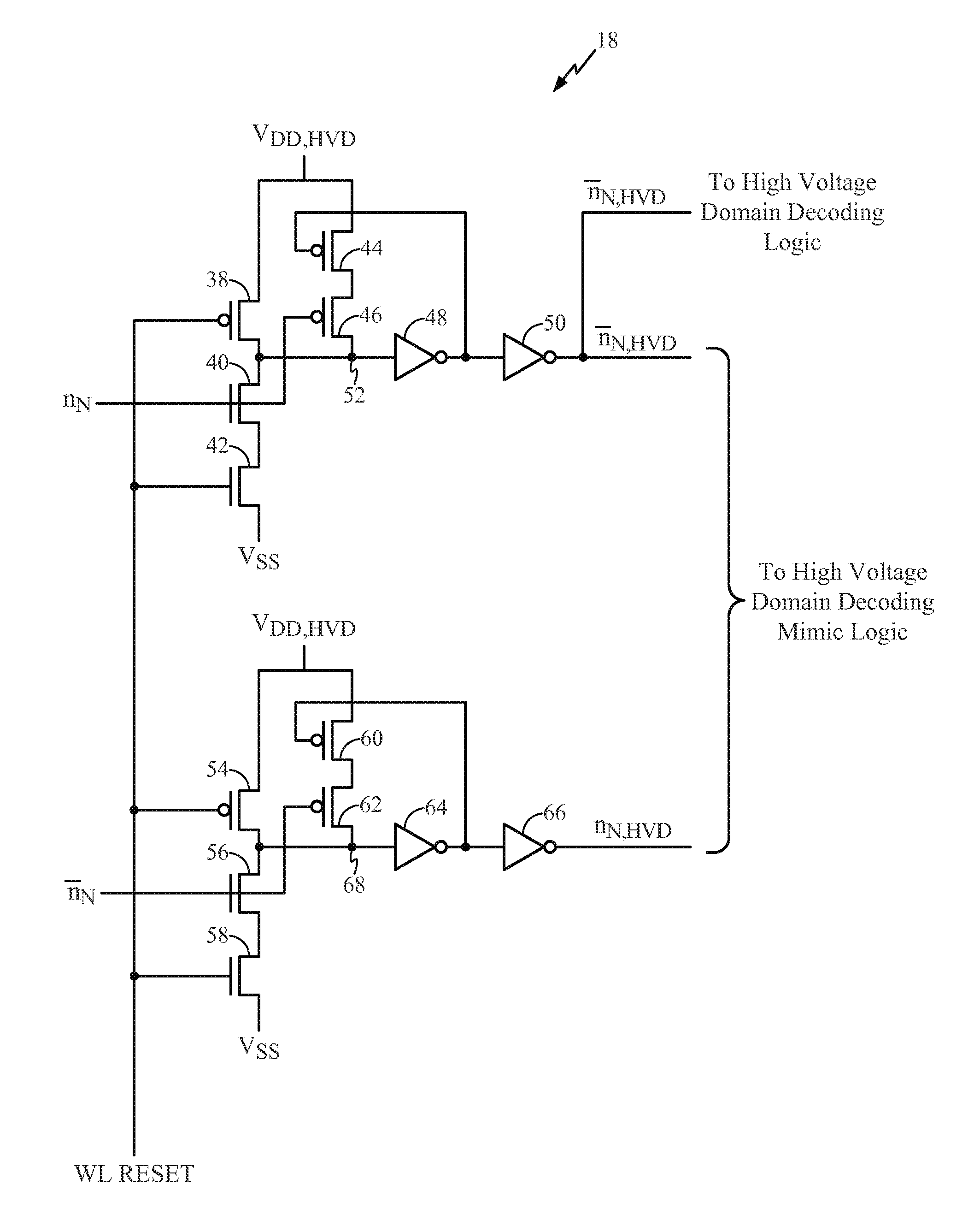
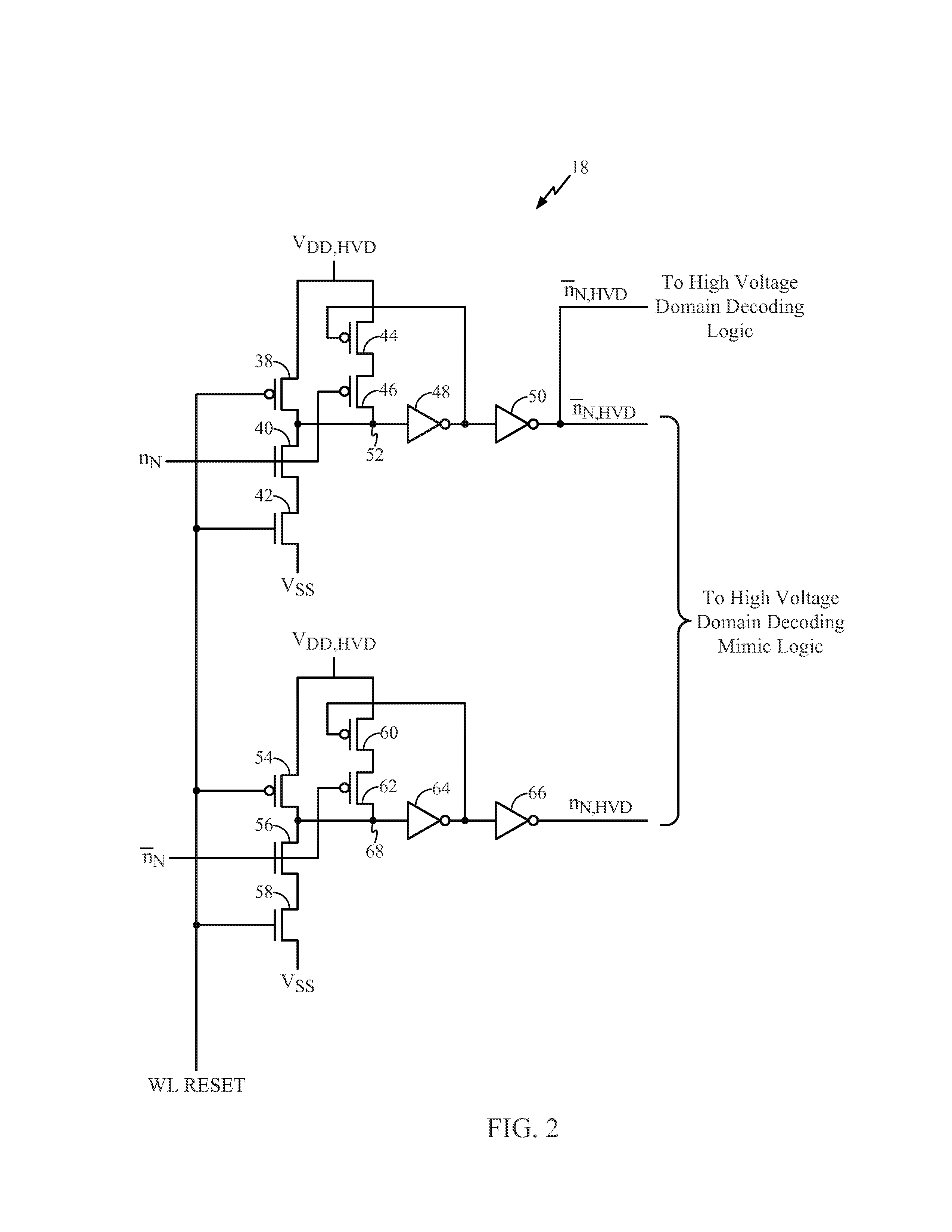
[0014]Systems and methods for adaptively mimicking wordline decoding logic for multi-voltage domain memory are disclosed. In one embodiment, the multi-voltage domain memory includes a memory array implemented in a high voltage domain and a multi-voltage domain control circuit. The multi-voltage domain control circuit includes multi-voltage domain decoding logic that generates a wordline for the memory array and a multi-voltage domain mimic logic that mimics the multi-voltage domain decoding logic to generate a dummy wordline. Preferably, the multi-voltage domain control circuit includes multiple multi-voltage domain decoding logic circuits...


PUM


Abstract

Systems and methods for adaptively mimicking wordline decoding logic for multi-voltage domain memory are disclosed. In one embodiment, the multi-voltage domain memory includes a memory array implemented in a high voltage domain and a multi-voltage domain control circuit. The multi-voltage domain control circuit includes multi-voltage domain decoding logic that generates a wordline for the memory array and a multi-voltage domain mimic logic that mimics the multi-voltage domain decoding logic to generate a dummy wordline. In one embodiment, the dummy wordline is utilized to trigger an ending edge (e.g., a falling edge) of the wordline once the wordline is asserted. In addition or alternatively, the dummy wordline is utilized to generate one or more control signals for the memory array such as, for example, a pre-charge control signal and / or a sense amplifier enable signal.

Description

PRIORITY CLAIM[0001]The present application claims priority to U.S. Patent Provisional Application Ser. No. 61 / 587,214 filed on Jan. 17, 2012 and entitled MIMICING MULTI-VOLTAGE DOMAIN WORDLINE DECODING LOGIC FOR A MEMORY ARRAY, which is incorporated herein by references in its entirety.FIELD OF THE DISCLOSURE[0002]The present disclosure relates to multi-voltage domain wordline decoding logic for a memory array and more specifically relates to mimicking multi-voltage domain wordline decoding logic for a memory array.BACKGROUND[0003]Particularly for mobile devices, power consumption is a major issue. Memory is one component for which a reduction in power consumption is desired. Modern low power memory designs typically include multiple voltage domains, which include a low voltage domain for wordline decoding logic and a high voltage domain for the memory array and read and write circuits. Specifically, due to relatively high minimum voltage requirements, the memory array must use a h...

Claims


Application Information

Patent Timeline
Patent Type & Authority Applications(United States)
IPC IPC(8): G11C7/12G11C8/10G11C7/00
CPCG11C8/08G11C7/227G11C7/12G11C7/22G11C8/10
Inventor GE, SHAOPINGCHAI, CHIAMINGLILES, STEPHEN E.NGUYEN, LAM V.FISCHER, JEFFREY HERBERT
Owner QUALCOMM INC
Learn More