
Bill transmission channel device

Inactive Publication Date: 2012-07-05
GRG BAKING EQUIP CO LTD
View PDF3 Cites 6 Cited by
  • Summary
  • Abstract
  • Description
  • Claims
  • Application Information

AI Technical Summary

Benefits of technology

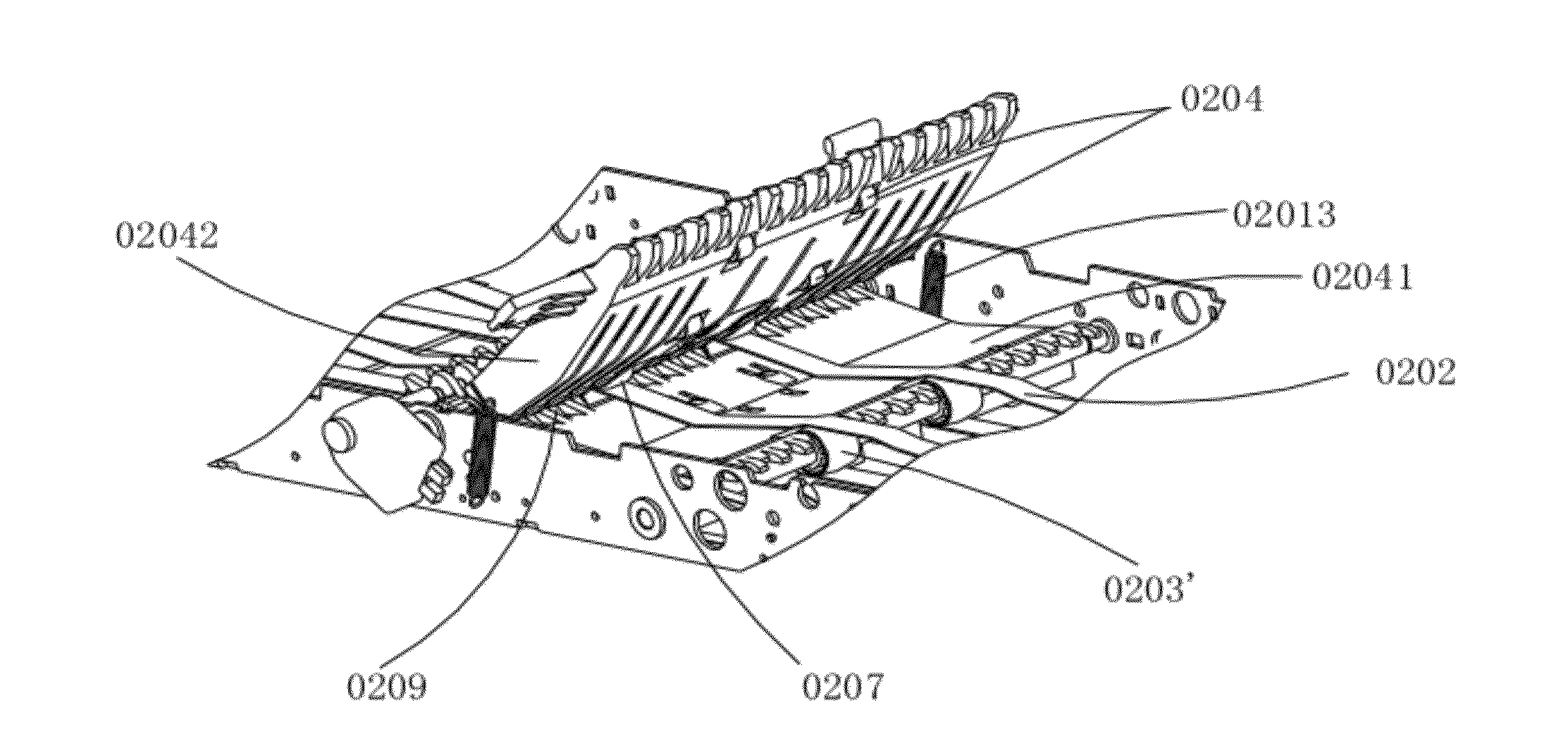
[0016]Preferably, an elastic member is arranged at the end with the spring of each of the independent boards and on a side that faces the cash boxes, and the elastic member is adapted to secure a stable positional relationship between the conveying channel device and the cash boxes.
[0019]Therefore, the banknote conveying channel device provided by the invention has the following advantages over the prior art:
[0020]1. The floating wheel arranged in the redirection locations may increase the force on the banknote being redirected, so that banknotes can be brought into the horizontal channel device smoothly from the upper machine interior after being sorted.
[0021]2. By the spring connection of the grouped channel boards, the coupling relationship between the channel boards and the channel support is secured. Accordingly, cash deposit and withdrawal are enabled even if the case cash box rack is not fully filled with cash boxes, thereby improving operational performance of the machine and utilization of cash boxes.

Problems solved by technology

This conveying method needs a lot of space and may cause banknote jams, hence deteriorating reliability of the cash recycling machine as a whole.
For the conventional conveying channel device to work properly, its cash box rack has to be fully filled with cash boxes, inevitably affecting operational performance and efficiency of the machine and utilization of cash boxes.

Method used


Image

  • Bill transmission channel device
  • Bill transmission channel device
  • Bill transmission channel device

Examples


Embodiment Construction

[0029]Technical solutions of the embodiments of the invention are clearly and fully described below in connection with the figures of the embodiments of the invention. It should be noted that the embodiments described herein are only some of the possible embodiments of the invention. Other embodiments, which are obtained by those skilled in the art based on the embodiments described herein without inventive efforts, should be included in the scope of the invention.

[0030]Now refer to FIG. 1, a structural diagram of a machine interior of an automated cash deposit and withdrawal machine provided by an embodiment of the invention. The machine interior includes an upper machine interior, which further includes a banknote identification module 011 and a sorting module 012, a banknote conveying channel 02, and a lower machine interior which includes multiple cash boxes. After banknotes 10 are put into the automated cash deposit and withdrawal machine, the banknotes 10 are sorted by the sor...


PUM

PropertyMeasurementUnit
Speedaaaaaaaaaa

Abstract

A bidirectional bill transmission channel device (02) with multi-path steering, which is arranged between an upper core (01) having functions of recognizing and separating bill and a lower core (03) for storing bill, is used for transmitting and separating bill in a reversing way. The device (02) comprises a channel bracket (0200), a power shaft (0203) mounted on the channel bracket (0200), a transmission belt (0202), channel boards (02041, 02042), an auxiliary transmission wheel set (0205) and a corner guide plate (0210), wherein floating wheels (0211, 0211′) are provided in a steering transmission route formed by the corner guide plate (0210) and the power shaft (0203), the floating wheels (0211, 0211′) correspond to the power shaft (0203) for transmission belt (0202), and form rolling friction assembly with the belt (0202).

Description

[0001]This application claims the benefit of Chinese patent application No. 200910192288.6 titled “Banknote Conveying Channel Device” and filed with the State Intellectual Property Office on Sep. 11, 2009, which is hereby incorporated by reference in its entirety.FIELD OF THE INVENTION[0002]The present invention relates to a banknote conveyor, and in particular, to a two-way banknote conveying channel device with multipath redirection.BACKGROUND OF THE INVENTION[0003]Conventional self-serving financial terminals include: automated cash deposit machines, automated cash withdrawal machines, and automated cash deposit and withdrawal machines. To realize banknote exchange between users and machines, all these paper money handling machines are equipped with a banknote conveying channel device, which is used to convey banknotes that the user wants to deposit to the vault, and / or convey banknotes from the vault to the user.[0004]Particularly, the banknote conveying channel device in an aut...

Claims


Application Information

Patent Timeline
IPC IPC(8): B65H5/26
CPCB65H29/00B65H2701/1912B65H2403/942B65H2403/20B65H29/12B65H29/52B65H29/58B65H31/24B65H3/44B65H5/025B65H5/38B65H2301/3121B65H2404/25B65H2404/2611B65H2404/2612B65H2404/262B65H2404/268B65H2404/2682B65H2404/612B65H2404/632B65H2405/331B65H2601/11B65H83/025G07D11/16
Inventor JIANG, ZHUANGLIU, ZHIYONGTAN, DONG
Owner GRG BAKING EQUIP CO LTD
Learn More