
Capacitive Touch Display Device

a display device and capacitive technology, applied in the field of capacitive touch display devices, can solve the problems of bad touch position accuracy and signals on the receiving electrodes, and achieve the effect of enhancing signal inducemen

Inactive Publication Date: 2013-07-18
NOVATEK MICROELECTRONICS CORP
View PDF5 Cites 21 Cited by
  • Summary
  • Abstract
  • Description
  • Claims
  • Application Information

AI Technical Summary

Benefits of technology

The present invention is about a capacitive touch display device that improves signal induction by opening holes on the receiving electrodes. The technical effect of this invention is that it enhances the sensitivity and responsiveness of the device.

Problems solved by technology

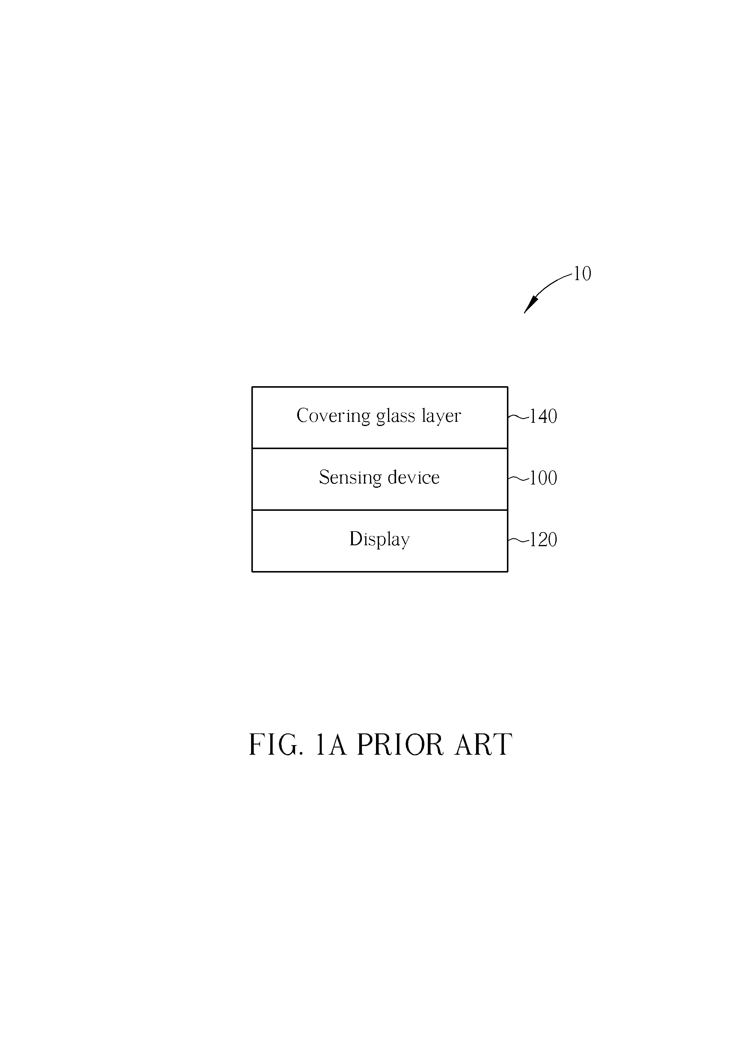
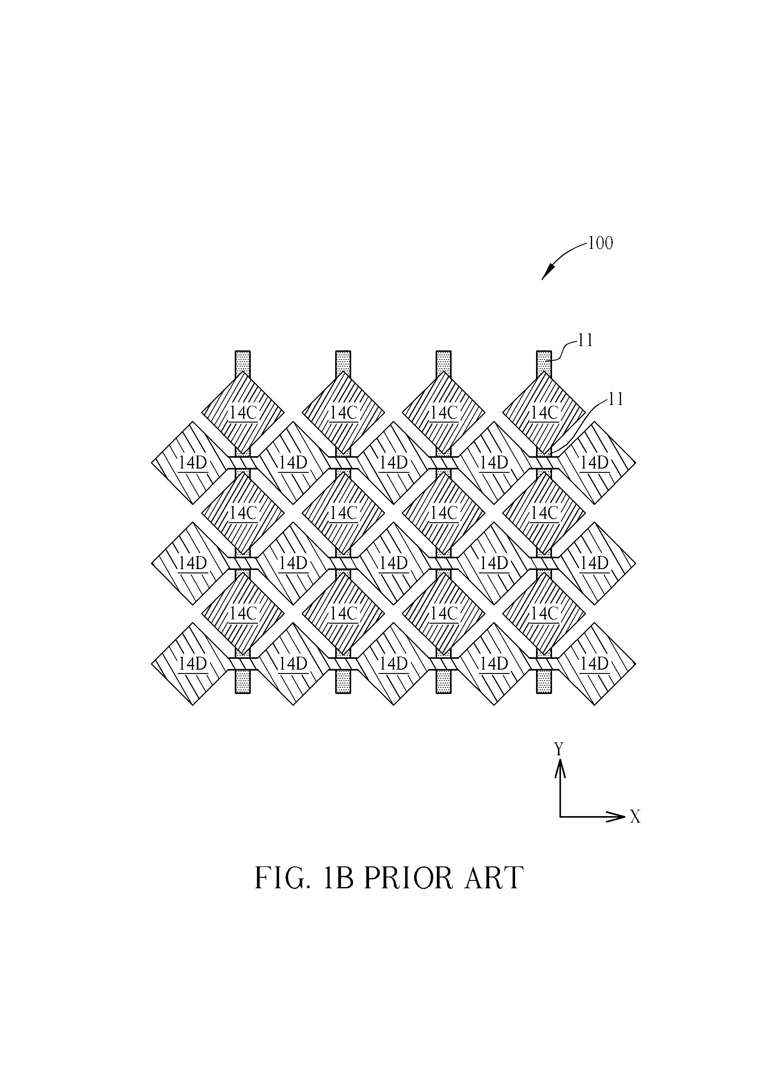
However, the sensing device 200 having the double-layer structure in FIG. 2A and FIG. 2B may reduce receiving the noise, but the driving signals usually have a small signal intensity or a small voltage, and thus the induced signals on the receiving electrodes 24C are even weaker, which leads to a bad accuracy of the touch position.
Therefore, how to improve the signal intensities of the induced signals such that the capacitive touch display device may determine the touch position more precisely and easily has become a critical issue in the industry.

Method used


Image

  • Capacitive Touch Display Device
  • Capacitive Touch Display Device
  • Capacitive Touch Display Device

Examples


Embodiment Construction

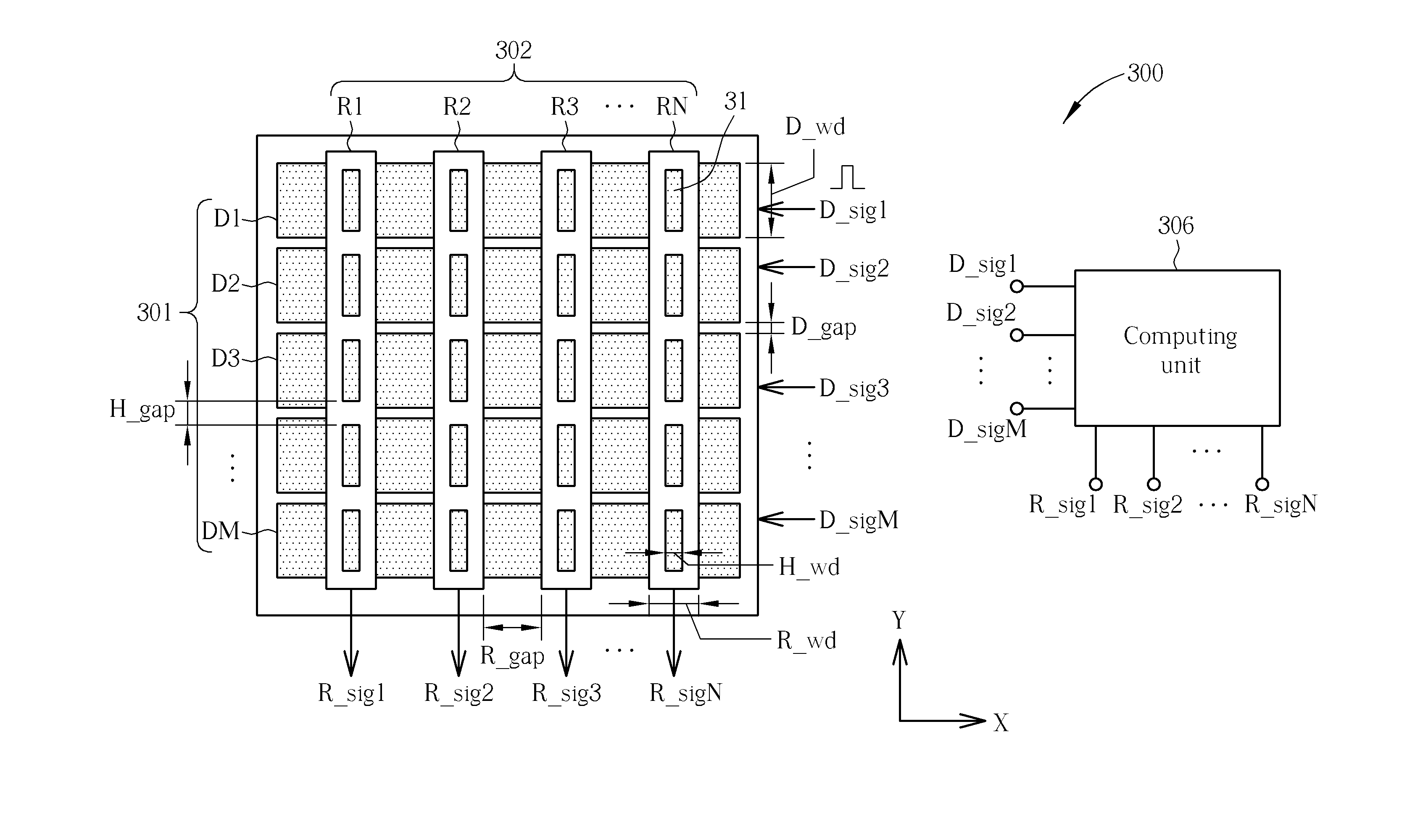
[0026]Please refer to FIG. 3, which is a schematic diagram of a sensing device 300 for a capacitive touch display device according to an embodiment of the present invention. A double-layered structure of the sensing device 300 is similar to a structure of the sensing device 200, i.e. the sensing device 300 comprises a driving signal layer 301 and an inducing signal layer 302. The driving signal layer is disposed on a display of the capacitive touch display device. The receiving signal layer is disposed between the driving signal layer 301 and a covering glass layer of the capacitive touch display device to avoid the receiving electrodes completely being exposed to the noise source, i.e. the display. As shown in FIG. 3, the driving signal layer 301 includes driving electrodes D1-DM, the receiving signal layer 302 includes receiving electrodes R1-RN. The driving electrodes D1-DM are used for transmitting driving signals Dsig1-DsigM. The receiving electrodes R1-RN are used for inducing...


PUM


Abstract

A capacitive touch display device is disclosed. The capacitive touch display device includes a display, a covering glass layer, and a sensing device including a driving signal layer disposed on the display, the driving signal layer including a plurality of driving electrodes, for outputting a plurality of driving signals, and a receiving signal layer disposed between the covering glass layer and the driving signal layer, the receiving signal layer including a plurality of receiving electrodes, for inducing the plurality of driving signals and outputting a plurality of touch sensing signals accordingly, wherein the plurality of receiving electrodes includes at least one hole for enhancing signal inducement.

Description

BACKGROUND OF THE INVENTION[0001]1. Field of the Invention[0002]The present invention relates to a capacitive touch display device, and more particularly, to a capacitive touch display device having holes in the receiving electrodes to enhance signal inducement.[0003]2. Description of the Prior Art[0004]A touch display device provides intuitional and easy operations and has been widely utilized among electrical products. A capacitive touch display device has many advantages such as multi-touch points, high detection accuracy, high spatial resolution and durableness. For these reasons, the capacitive touch control is the most popular technique used today.[0005]The touch control display device includes a display panel and a transparent touch panel. Through attachment of the display panel to the transparent touch panel, the touch control display device can realize functions of touch control as well as display. Capacitive touch control techniques detect capacitance changes caused by hum...

Claims


Application Information

Patent Timeline
Patent Type & Authority Applications(United States)
IPC IPC(8): G06F3/044
CPCG06F3/044G06F3/0445G06F3/0446G06F3/0448
Inventor LAI, CHIH-CHANGLI, JYUN-SIAN
Owner NOVATEK MICROELECTRONICS CORP
Learn More