
System and process for an active drain for gas-liquid separators

a gas-liquid separator and active drain technology, which is applied in the direction of liquid degasification, separation process, liquid degasification regulation/control, etc., can solve the problems of cyclonic separators that are not perfect, loss of sample, and possible contamination of downstream components, so as to achieve better deterministic draining

Active Publication Date: 2013-07-18
AGILENT TECH INC
View PDF1 Cites 30 Cited by
  • Summary
  • Abstract
  • Description
  • Claims
  • Application Information

AI Technical Summary

Benefits of technology

This patent describes a new way to drain liquid from a gas-liquid separator. Rather than using traditional methods, this invention uses a special pump to control the flow of liquid in real-time, regardless of pressure or viscosity. This new method is particularly useful in chromatography and extraction techniques that require precise and controlled liquid drainage.

Problems solved by technology

Supercritical fluid extraction (SFE) is a related technique but with somewhat lower requirements for accurate flow or pressure control.
Several problems exist with the recovery of purified liquid fractions from gas-liquid separators used in preparative supercritical fluid chromatography [SFC] systems.
Cyclonic separators were not perfect, and a percentage of the original aerosol, containing valuable analytes held in suspension, typically found a path to the vent as well, causing loss of sample and possible contamination of downstream components.
Further, the separators were expensive and had to be built for a specific capacity (typically less than one-third of the container volume) to allow sufficient room for expansion of the entering vapor cloud.
One means was by opening a valve which released the C02-saturated liquid to an external container, which caused a violent outgassing and potential rupture of the container.
A second means was to depressurize the container, then empty it, which was inefficient and time consuming.
Finally, because the collection process deposits thin films of solute-laden liquid on the walls, each separator must be thoroughly cleaned (typically manually) before re-use with a different collection peak, which again was inefficient and time-consuming.
The serial nature of collection through cyclonic separators can introduce an additional difficulty.
Missing the time window by as much as a few seconds can cause contamination of the previously pooled fractions and require repurification.
Factors that can vary this timing can dramatically interfere with both recovery and purity of collected fractions.
However, a problem arises for gradient separations which constitute the primary intended use of the system.
The unrestrictive line will pass a significant amount of vapor under these conditions and potentially cause difficulty at the probe due to spraying.
Thus it is very difficult to time the start and stop of collection at the probe tip.
The problem becomes much worse as the user varies modifier viscosity.
As a result, the flow of vapor through the tube is rather limited.
Now at least ten times more vapor is released to the probe and can cause serious problems with timing, dispensing and aerosol formation.
The result is a significantly less flexible system than desired with unnecessarily large fractions collected due to the makeup flow.

Method used


Image

  • System and process for an active drain for gas-liquid separators
  • System and process for an active drain for gas-liquid separators
  • System and process for an active drain for gas-liquid separators

Examples


Embodiment Construction

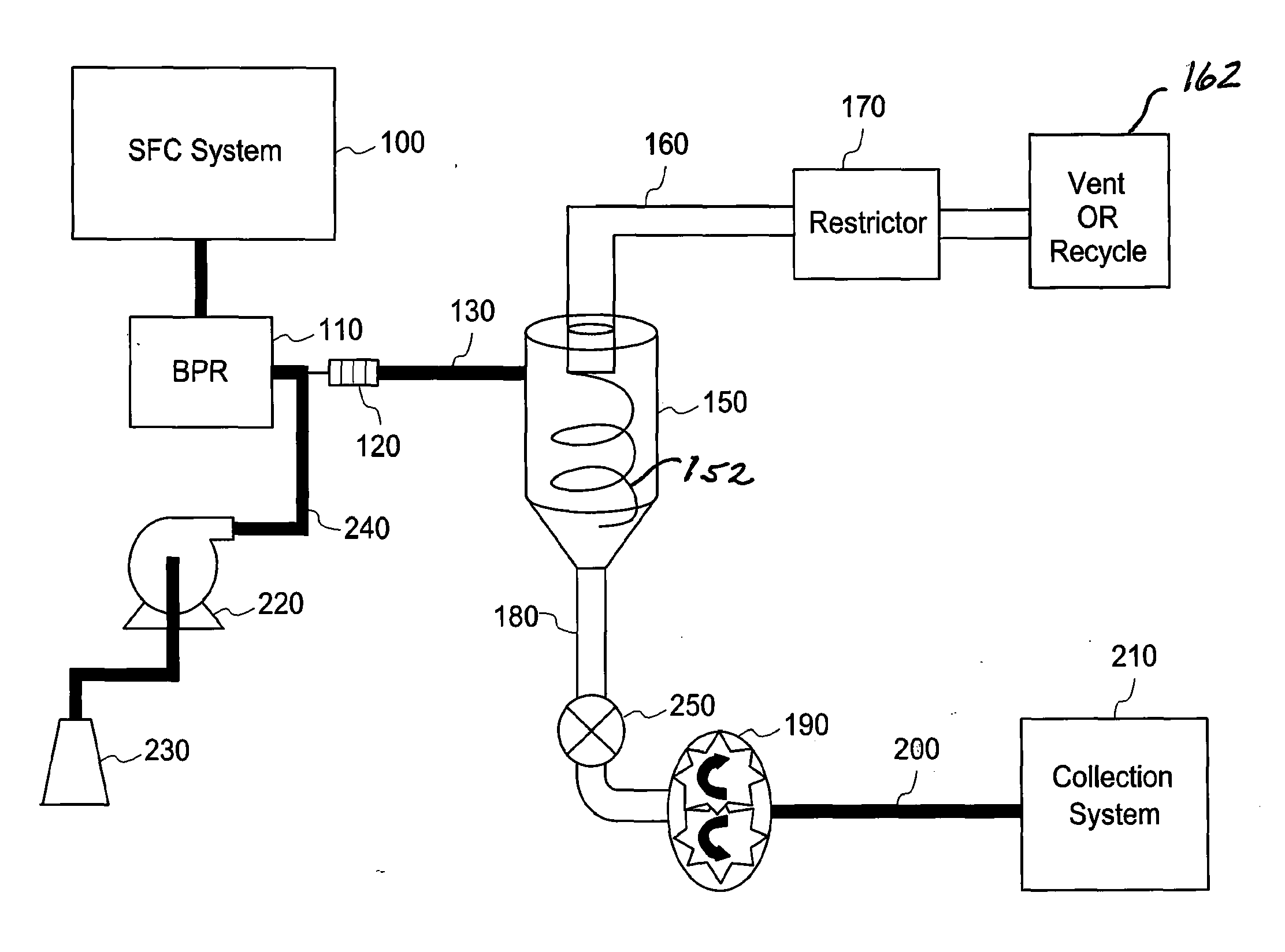
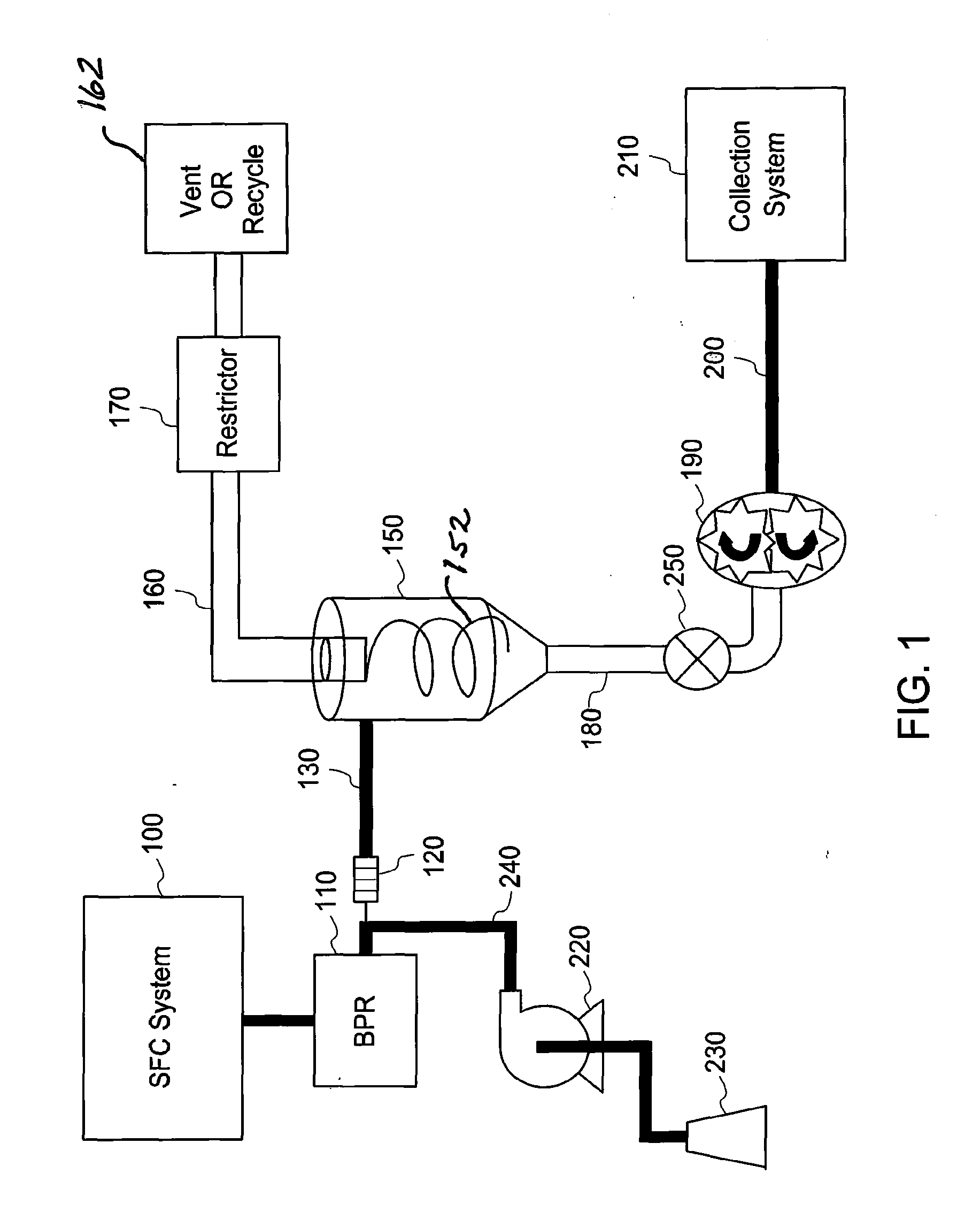
[0031]FIG. 1 illustrates a schematic process flow diagram of an illustrative embodiment that includes the collection end of a preparative SFC system. In this figure, chromatographic SFC system 100 is comprised of necessary fluid sources, pumps, injectors, separation columns and detectors to effectively allow injection of a sample mixture into the system and create a time and flow segment separated stream of “peaks” containing individual dissolved compounds of interest. The fluid carrier, or mobile phase, of the flow stream is comprised of a mixture of near supercritical carbon dioxide, or equivalent carrier stream, and an organic modifier such as methanol, ethanol or isopropanol. The carbon dioxide (C02) is maintained well above its critical pressure during the chromatographic process by backpressure regulator (BPR) 110.

[0032]Immediately following BPR 110, the mobile phase experiences a large pressure drop typically on the order of 60 to 200 bars. This brings the C02 of the mobile p...


PUM

PropertyMeasurementUnit
densityaaaaaaaaaa
temperatureaaaaaaaaaa

Abstract

An apparatus and process to effectively create an active drain for high and low pressure gas-liquid separator. The invention accomplishes a deterministic drainage rate of variable volume and viscosity liquid fractions from the separator. The mechanisms and methods thereof create a flow path from the separator that dramatically favors controlled liquid flow over a wide range of flow rates and viscosities while restricting gas flow. The invention is a superior method of drainage over conventional systems that employ pressure, vacuum, isolation valves and / or passive flow restrictors to achieve drainage of the separators. The embodiments are primarily directed to the fields of preparative supercritical fluid chromatography (SFC) and supercritical fluid extraction (SFE). An advantage of one embodiment allows the economical conversion of typical HPLC systems to state of-the-art supercritical fluid chromatography (SFC) systems with minimal modification to system components.

Description

STATEMENT OF PRIORITY[0001]The present application is a U.S. national phase application under 35 USC §371(c) of International Application Pub. No. WO / 2012 / 040252 filed on Sep. 20, 2011, naming K. Fogelman et al. as inventors. The entire disclosure of International Application Pub. No. WO / 2012 / 040252 is hereby incorporated by reference in its entirety. This application claims the benefit of U.S. Provisional Application No. 61 / 384,318 filed 20 Sep. 2010.FIELD OF THE INVENTION[0002]The present invention relates to systems and processes for high and low pressure gas-liquid separators.BACKGROUND[0003]Supercritical fluid chromatography (SFC) is a separation technique similar to high performance liquid chromatography (HPLC), except one of the fluids used as a solvent is a highly compressible liquefied gas. Supercritical fluid extraction (SFE) is a related technique but with somewhat lower requirements for accurate flow or pressure control. The most common fluid used in SFC (and SFE) is car...

Claims


Application Information

Patent Timeline
Patent Type & Authority Applications(United States)
IPC IPC(8): B01D19/00
CPCB01D15/40B01D19/0036B01D19/0063B01D19/0057B01D15/10
Inventor FOGELMAN, KIMBER D.WIKFORS, EDWIN E.BERGER, TERRY A.
Owner AGILENT TECH INC
Learn More