Power supplying module for contactless power supplying device, method for using power supplying module of contactless power supplying device, and method for manufacturing power supplying module of contactless power supplying device

a technology of power supply module and power supply module, which is applied in the direction of magnets, inductances, magnetic bodies, etc., can solve the problems of complex structure high cost of each power supply module, and high degree of freedom of design. , the effect of easy manufacturing and short period of tim

Active Publication Date: 2013-07-11
PANASONIC INTELLECTUAL PROPERTY MANAGEMENT CO LTD
View PDF10 Cites 194 Cited by
  • Summary
  • Abstract
  • Description
  • Claims
  • Application Information

AI Technical Summary

Benefits of technology

[0007]It is an object of the present invention to provide a power supplying module for a contactless power supplying device, a method for using the power supplying module of the contactless power supplying device, and a method for manufacturing the power supplying module of the contactless power supplying device that has a high degree of freedom for design, allows for contactless power supply in various modes, and enables manufacturing that is easy and performed within a short period of time.
[0034]The present invention provides a power supplying module for a contactless power supplying device having a high degree of freedom for design, allowing for contactless power supply in various modes, and enabling manufacturing that is easy and performed within a short period of time.

Problems solved by technology

The power supplying circuit is thus a complex and expensive power supplying module.
Furthermore, each power supplying module has a complex structure since a commercial power supply is input to each power supplying module.
Therefore, each power supplying module is very expensive.
The task of assembling the complex power supplying modules on the transfer route is very cumbersome and requires effort and time.
Therefore, there is a limitation to the freedom of design for an area where the power supplying modules can be laid out and supplied with power.

Method used


Image

  • Power supplying module for contactless power supplying device, method for using power supplying module of contactless power supplying device, and method for manufacturing power supplying module of contactless power supplying device
  • Power supplying module for contactless power supplying device, method for using power supplying module of contactless power supplying device, and method for manufacturing power supplying module of contactless power supplying device
  • Power supplying module for contactless power supplying device, method for using power supplying module of contactless power supplying device, and method for manufacturing power supplying module of contactless power supplying device

Examples


first embodiment

[0069]A first embodiment of a contactless power supplying device according to a contactless power supplying system of the present invention will now be described with reference to the drawings.

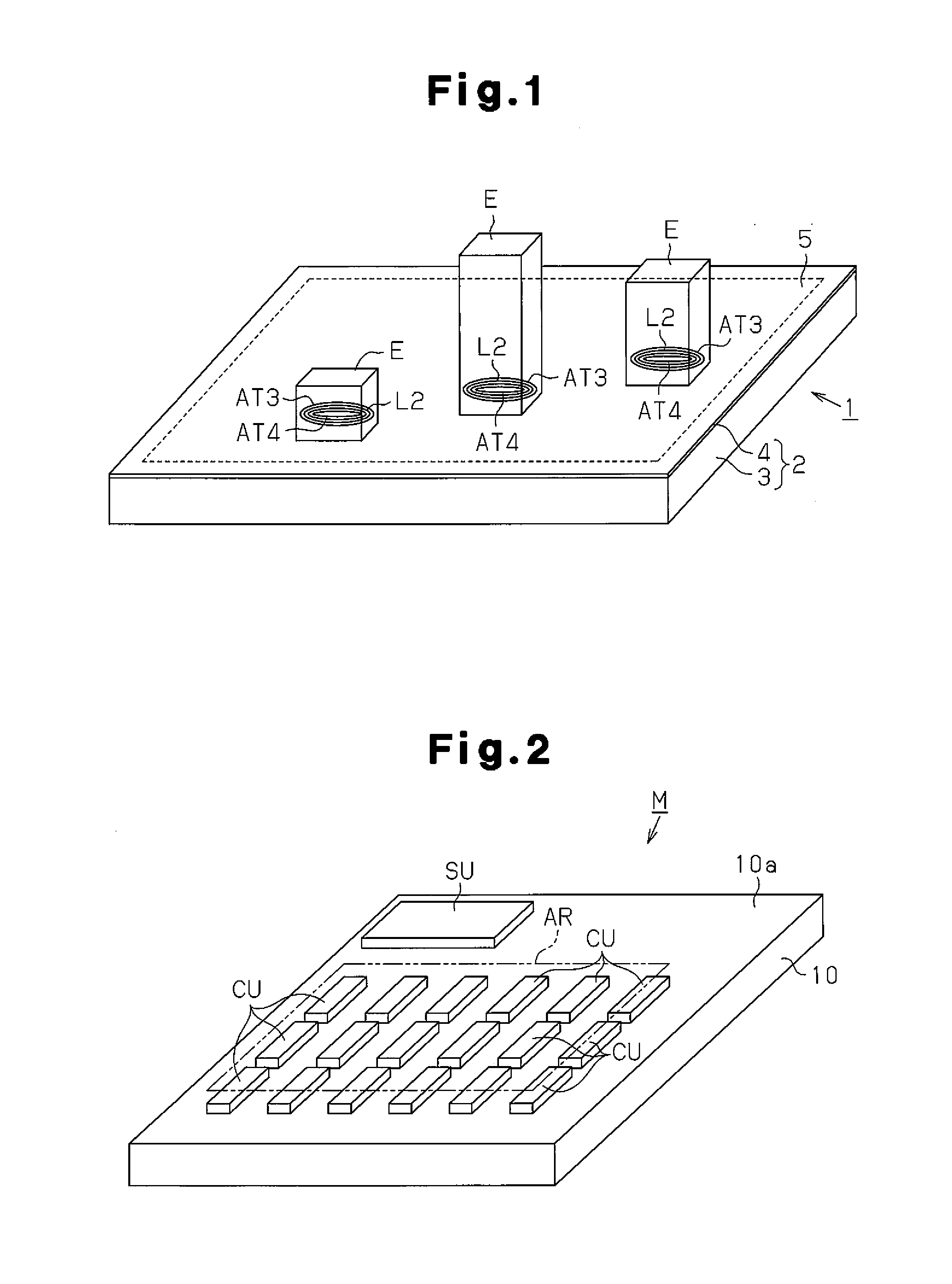
[0070]As shown in FIG. 1, a contactless power supplying device 1 includes a housing 2. The housing 2 includes a tetragonal box body 3, which has an upper opening, and a top plate 4, which is formed by an insulating body and closes the opening of the box body 3. The top plate 4 includes a setting surface 5, which is an upper surface of the contactless power supplying device 1 for mounting a device E to supply power in a contactless manner.

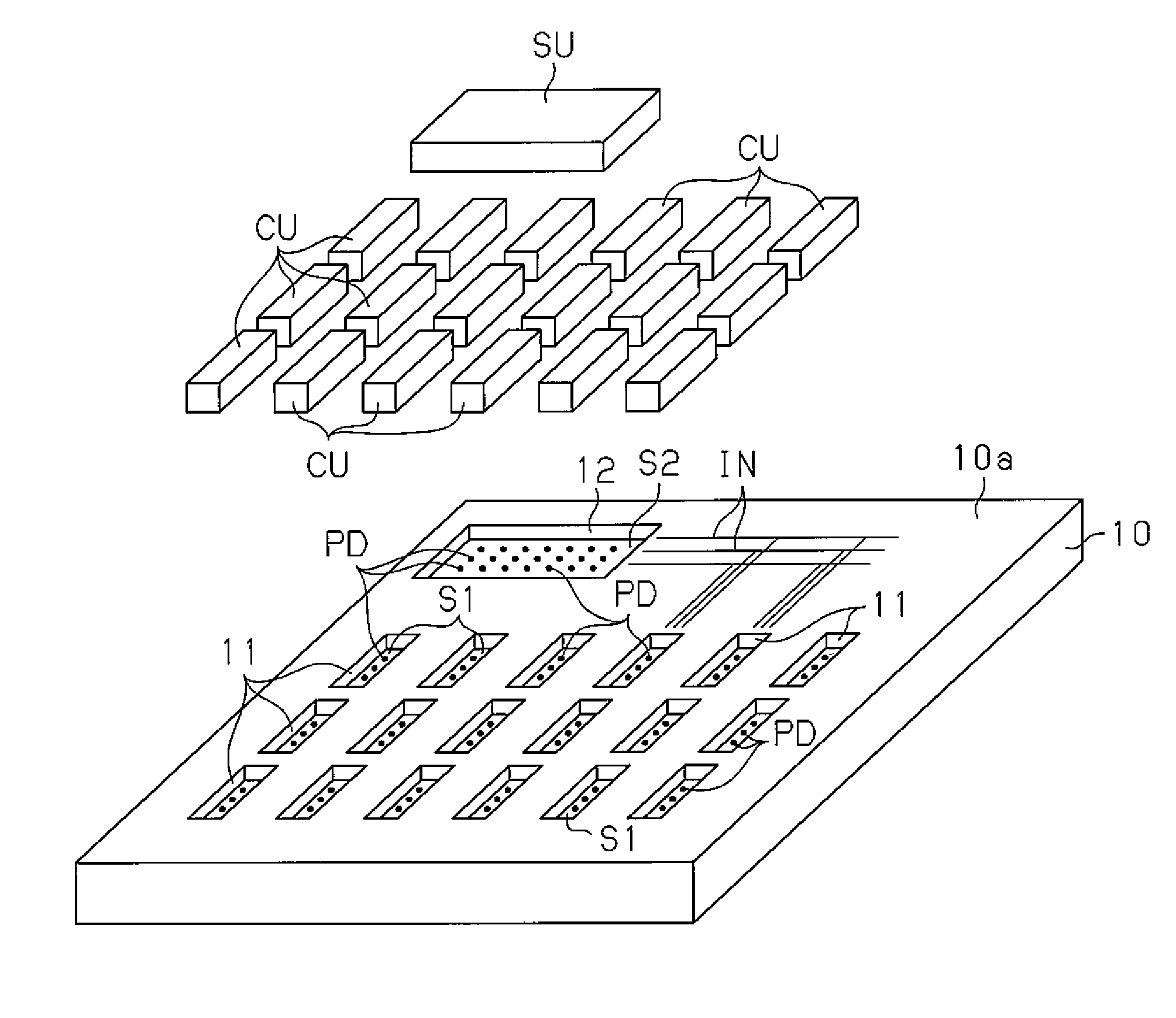
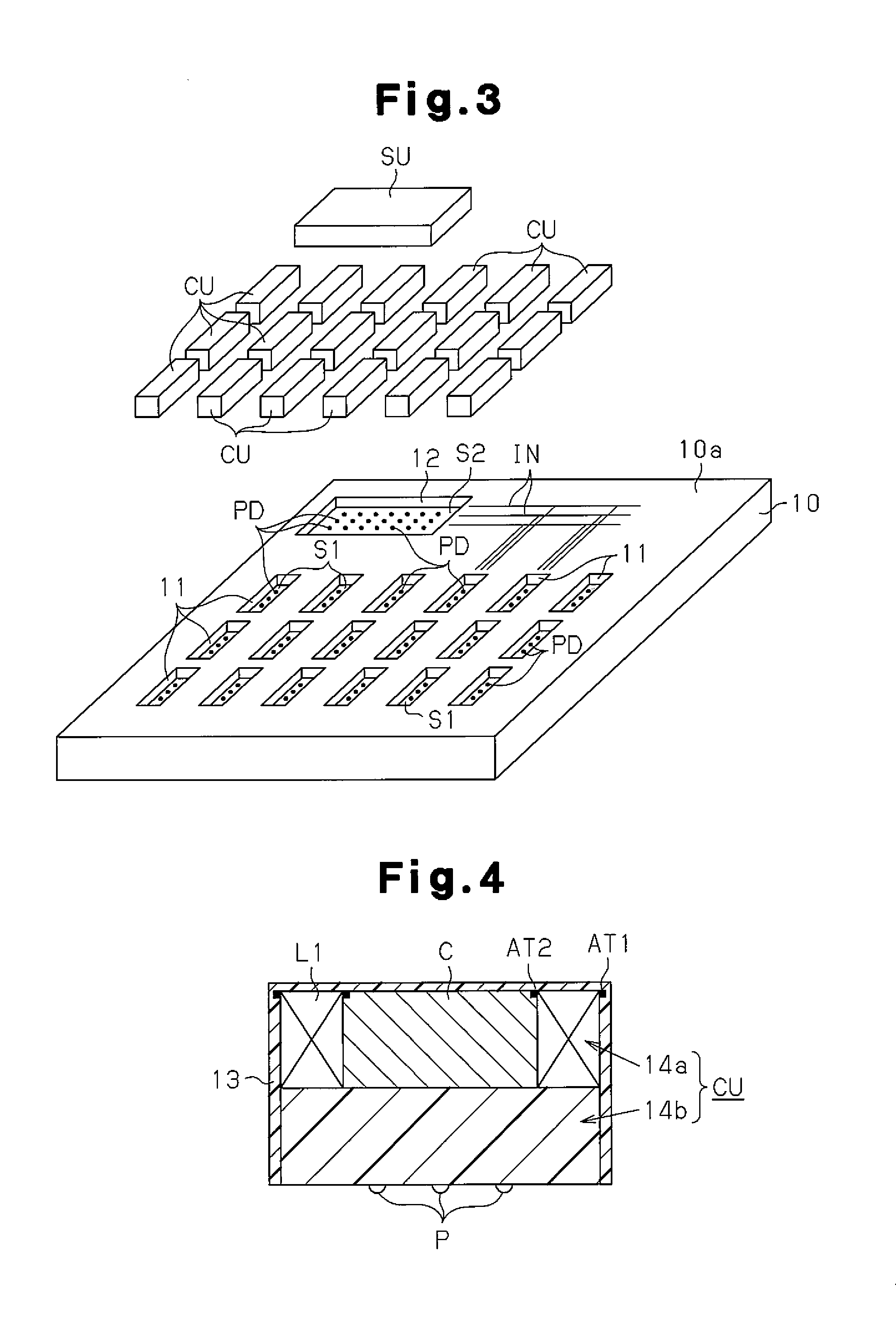
[0071]As shown in FIG. 2, a power supplying module M is accommodated in the housing 2. The power supplying module M includes a printed wiring substrate 10, a plurality of coil units CU, and a system unit SU. The plurality of coil units CU are arranged on the printed wiring substrate 10 and electrically connected to the printed wiring substrate 10. The system u...

second embodiment

[0195]A second embodiment of the present invention will now be described.

[0196]The coil unit CU of the first embodiment is configured by the coil portion 14a and the drive portion 14b. In contrast, the coil unit of the second embodiment has the drive portion 14b omitted from the coil unit CU of the first embodiment.

[0197]As shown in FIG. 24, eight coil unit fitting recesses 11a are formed in the left-right direction at the back side of the upper surface 10a of the printed wiring substrate 10. Eight drive unit fitting recesses 11b and one system unit fitting recess 12 are formed in the left-right direction on the front side of the upper surface 10a of the printed wiring substrate 10.

[0198]Each coil unit fitting recess 11a has a rectangular shape extending in the front-back direction. The coil unit fitting recesses 11a are formed at equal pitches from the adjacent coil unit fitting recess 11a in the left-right direction. Each drive unit fitting recess 11b has a rectangular shape exten...


PUM

PropertyMeasurementUnit
distanceaaaaaaaaaa
diameteraaaaaaaaaa
anglesaaaaaaaaaa

Abstract

Coil units equipped with primary coils having the same specification are provided in a power feeding module. Coil-unit intermeshing recess sections are formed on a printed circuit board to match each of the coil units. Pads for joining together with electrodes formed on the coil units are formed on the bottom faces of each of the coil-unit intermeshing recess sections. A plurality of coil units can be mounted onto the printed circuit board easily, by fitting each of the coil units into each of the coil-unit intermeshing recess sections and joining them together, which will enable manufacturing efficiency to be improved.

Description

TECHNICAL FIELD[0001]The present invention relates to a power supplying module for a contactless power supplying device, a method for using the power supplying module of the contactless power supplying device, and a method for manufacturing the power supplying module of the contactless power supplying device.BACKGROUND ART[0002]In recent years, various types of practical systems that use a contactless power supplying technique have been proposed. For example, a large number of power supplying modules, each having a plurality of power supplying coils, are laid along a transfer route. A moving body including a power receiving coil is arranged on the transfer route. The moving body generates secondary power at the power receiving coil through electromagnetic induction resulting from excitation of the power supplying coils in the power supplying modules laid along the transfer route. The secondary power is used to drive, for example, a motor and thus move the moving body (patent documen...

Claims


Application Information

Patent Timeline
Patent Type & Authority Applications(United States)
IPC IPC(8): H04B5/00H05K13/04H01F27/28H01F38/14
CPCH04B5/0037Y10T29/4902H01F38/14H05K13/04H02J50/12H02J50/70H02J50/80H02J50/402H02J50/90H02J50/10H02J50/60
Inventor ABE, HIDEAKIYAGYU, HIROYUKITANAKA, WATARUABE, SHINICHI
Owner PANASONIC INTELLECTUAL PROPERTY MANAGEMENT CO LTD
Why Eureka
Try Eureka