Industrial vehicle
- Summary
- Abstract
- Description
- Claims
- Application Information
AI Technical Summary
Benefits of technology
Problems solved by technology
Method used
Image
Examples
first embodiment
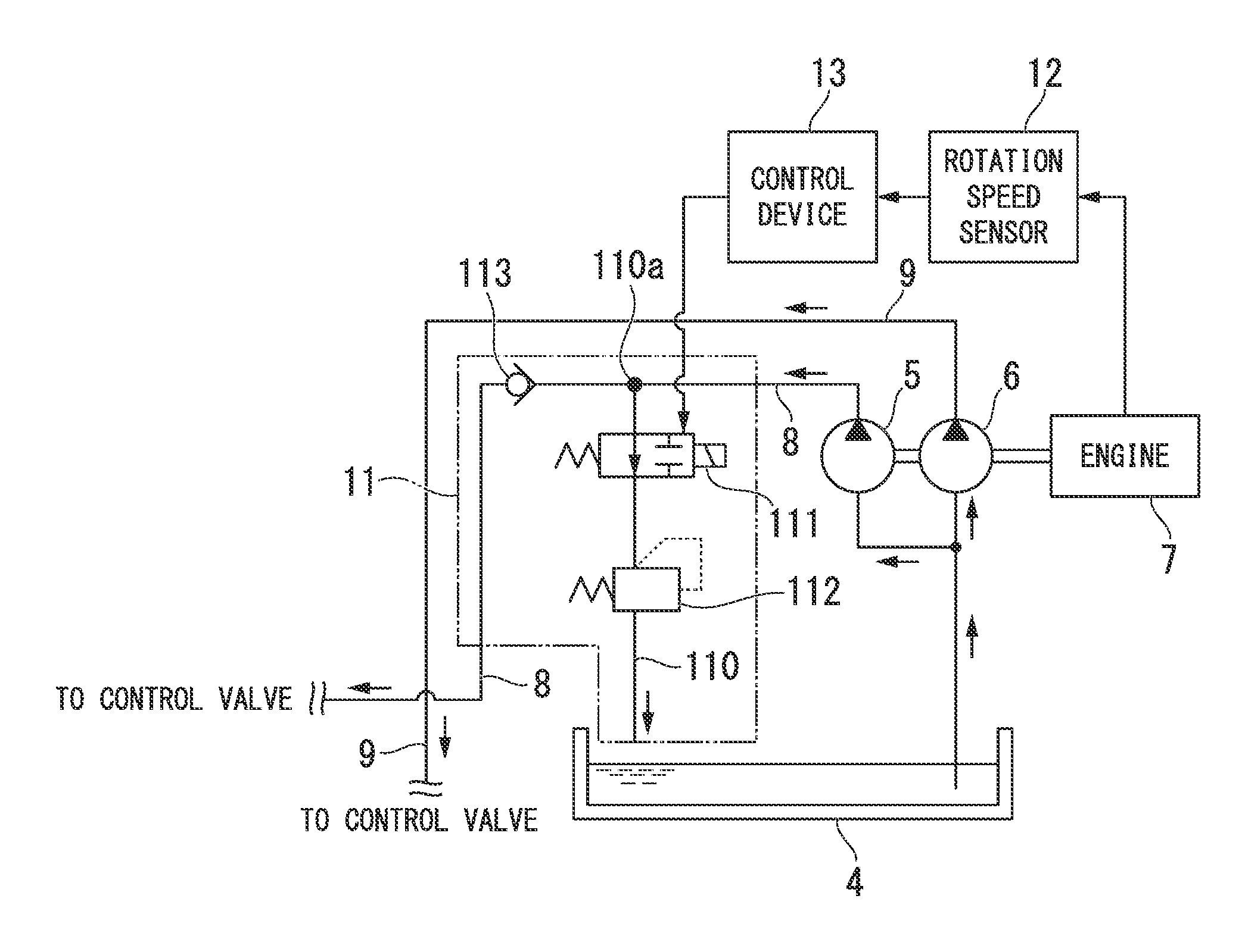
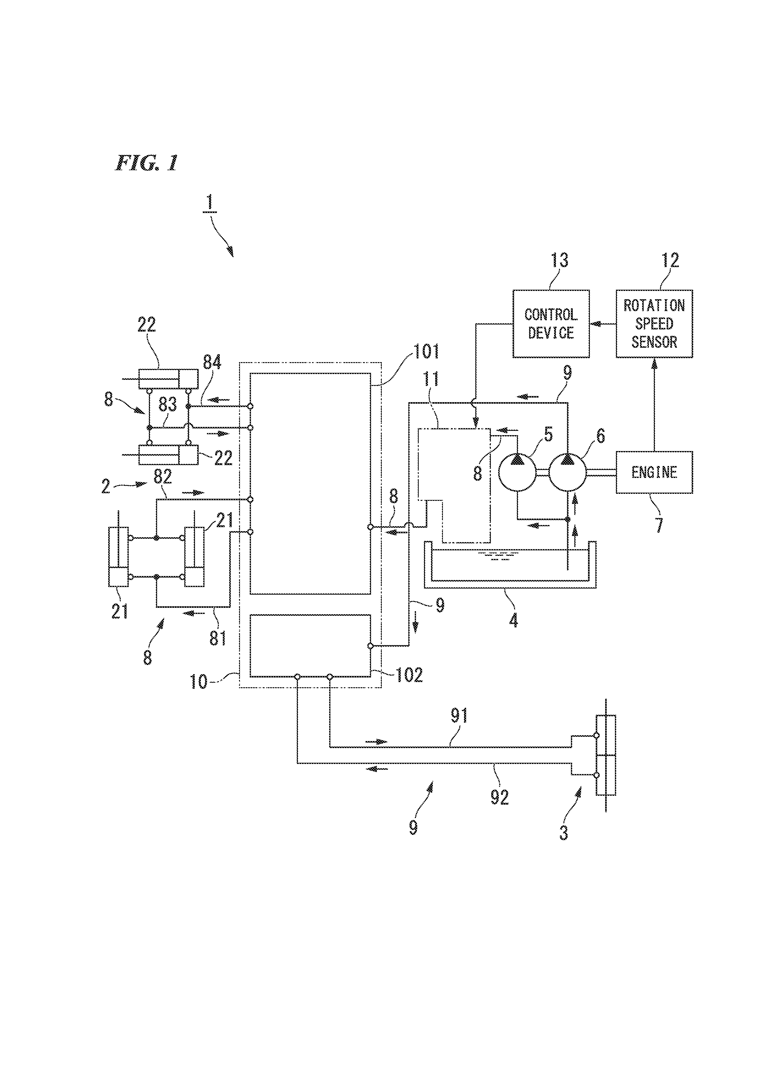
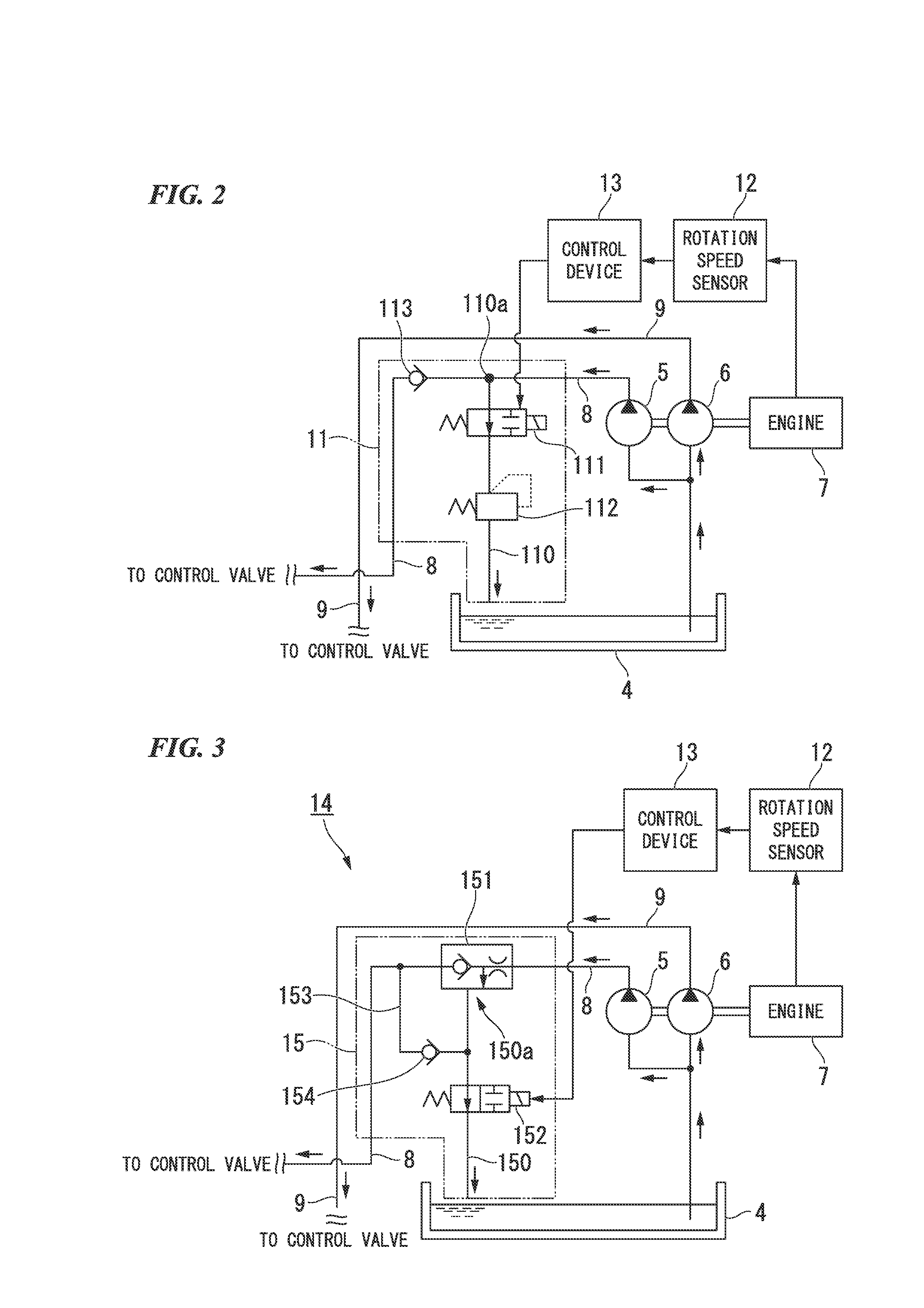
[0044]The pump load reduction system 11 is for adjusting a load which is applied to the pump for cargo handling 5, depending on the output of the engine 7. Here, FIG. 2 is a schematic diagram showing the detailed configuration of the pump load reduction system 11 regarding the forklift 1 according to the The pump load reduction system 11 has discharge piping 110, a switching valve 111, a sub-relief valve 112, and a check valve 113. The discharge piping 110 branches from the hydraulic piping for cargo handling 8 and is connected to the tank 4. The switching valve 111 is provided in the discharge piping 110. The sub-relief valve 112 is provided further to the downstream side than the switching valve 111 in the discharge piping 110. The check valve 113 is provided further to the downstream side than a branching position 110a of the discharge piping 110 in the hydraulic piping for cargo handling 8.
[0045]In addition, in this embodiment, the installation position of the sub-relief valve ...
second embodiment
[0062]Next, the operation and effects of the forklift 14 will be described. First, in a case where the flow rate of the hydraulic oil discharged from the pump for cargo handling 5 shown in FIG. 3 is smaller than a preset flow rate, the priority valve 151 makes all the flow rate flow to the hydraulic piping for cargo handling 8 on the downstream side. In this way, when the flow rate of the hydraulic oil is small and the load of the pump for cargo handling 5 is low, regardless of a level of the output of the engine 7, all of the hydraulic oil discharged from the pump for cargo handling 5 is supplied to the hydraulically-operated device for cargo handling 2 through the control valve 10 and all the pressure of the hydraulic oil is used to operate the hydraulically-operated device for cargo handling 2.
[0063]On the other hand, in a case where the flow rate of the hydraulic oil which is discharged from the pump for cargo handling 5 shown in FIG. 3 is greater than a preset flow rate, the p...
third embodiment
[0074]Next, the operation and effects of the forklift 16 will be described. First, in a case where the rotation speed of the engine 7 which is detected by the rotation speed sensor 12 shown in FIG. 4 is larger than a predetermined value, that is, in a case where the output of the engine 7 is high, the switching valve 171 subjected to control by the control section closes the discharge piping 170. Therefore, all of the hydraulic oil discharged from the pump for cargo handling 5 is supplied to the hydraulically-operated device for cargo handling 2 through the control valve 10. In this way, when the output of the engine 7 is high and an engine stall does not easily occur, all the pressure of the hydraulic oil which is discharged from the pump for cargo handling 5 is used to operate the hydraulically-operated device for cargo handling 2.
[0075]On the other hand, in a case where the rotation speed of the engine 7 is smaller than a predetermined value, that is, in a case where the output ...
PUM
 Abstract
Description
Claims
Application Information
 - R&D
- Intellectual Property
- Life Sciences
- Materials
- Tech Scout
- Unparalleled Data Quality
- Higher Quality Content
- 60% Fewer Hallucinations
Browse by: Latest US Patents, China's latest patents, Technical Efficacy Thesaurus, Application Domain, Technology Topic, Popular Technical Reports.
© 2025 PatSnap. All rights reserved.Legal|Privacy policy|Modern Slavery Act Transparency Statement|Sitemap|About US| Contact US: help@patsnap.com


