Eureka AIR delivers breakthrough ideas for toughest innovation challenges, trusted by R&D personnel around the world.

Wireless communication method and system for transmission authentication at the physical layer

Active Publication Date: 2013-06-27
US SEC THE ARMY THE +1
View PDF5 Cites 26 Cited by
  • Summary
  • Abstract
  • Description
  • Claims
  • Application Information

AI Technical Summary

Benefits of technology

The present invention provides an authentication scheme that is designed to be discreet, strong against interference, and secure for verifying identities. Additionally, it allows for concealing the authentication from bystanders, so they cannot detect any abnormalities in the signal or changes in their own performance as a result of the authentication. The authentication scheme is also more resistant to interference and can protect against being transparent to an adversary.

Problems solved by technology

However, data throughput is penalized since some of the bits carry authentication instead of data.
However, as opposed to the multiplexing approach, embedding of additional information degrades the data quality (I. J. Cox, M. L. Miller, and A. L. McKellips, “Watermarking as Communications with Side Information”, Proceedings of the IEEE, Volume 87, Issue 7, July 1999, pp.
While these techniques are covert and provide robustness to interference, they achieve this at the cost of bandwidth expansion.
Additionally, if it is desired to add authentication to a system in a stealthy way so that users unaware of the authentication continue to communicate without modifications to hardware or protocol, the technique does not serve this purpose well, since only authenticated parties with knowledge of the secret are allowed to participate in communications.
However, a subtle difference arises since the authentication signal may or may not be present in the received signal.

Method used


Image

  • Wireless communication method and system for transmission authentication at the physical layer
  • Wireless communication method and system for transmission authentication at the physical layer
  • Wireless communication method and system for transmission authentication at the physical layer

Examples


Embodiment Construction

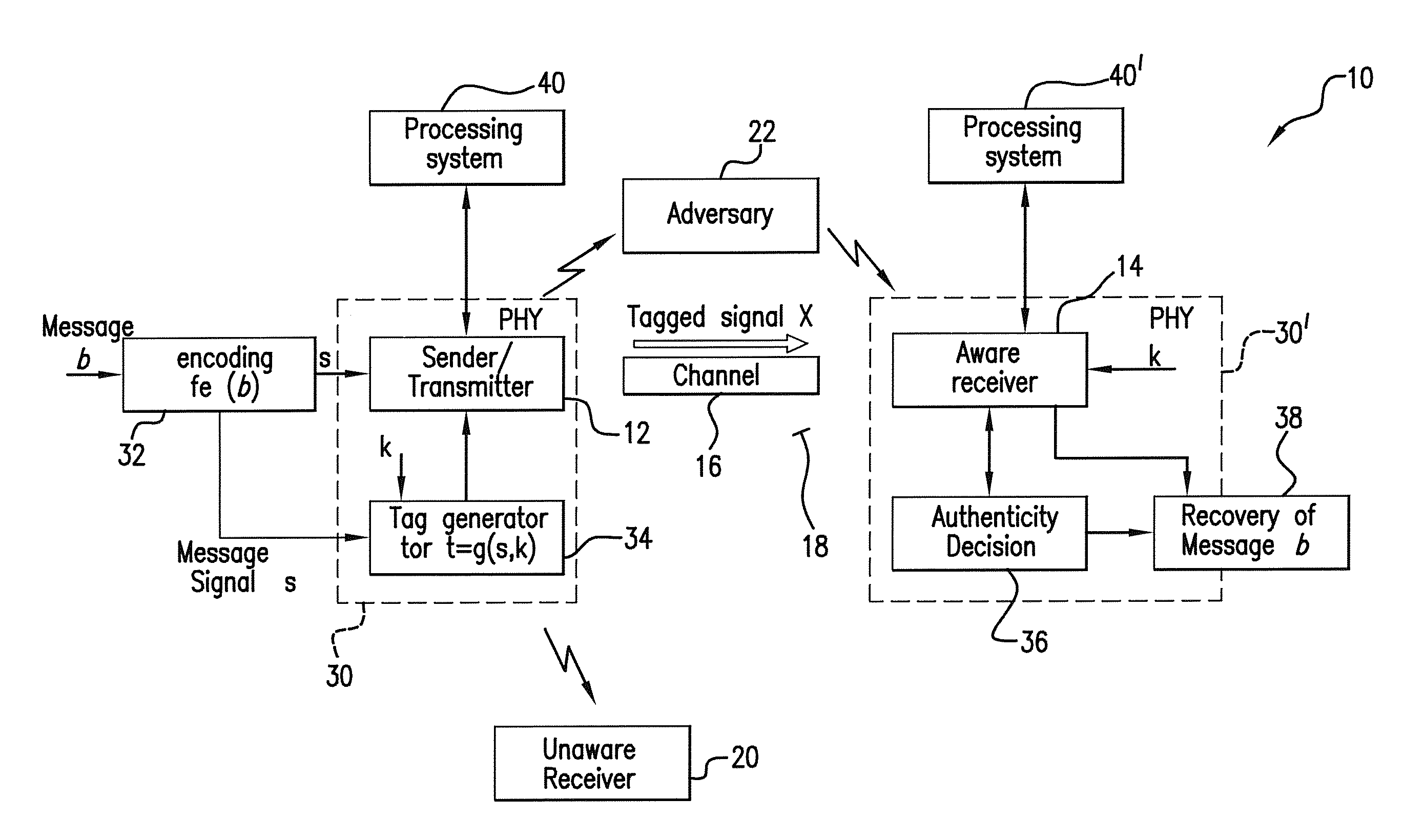
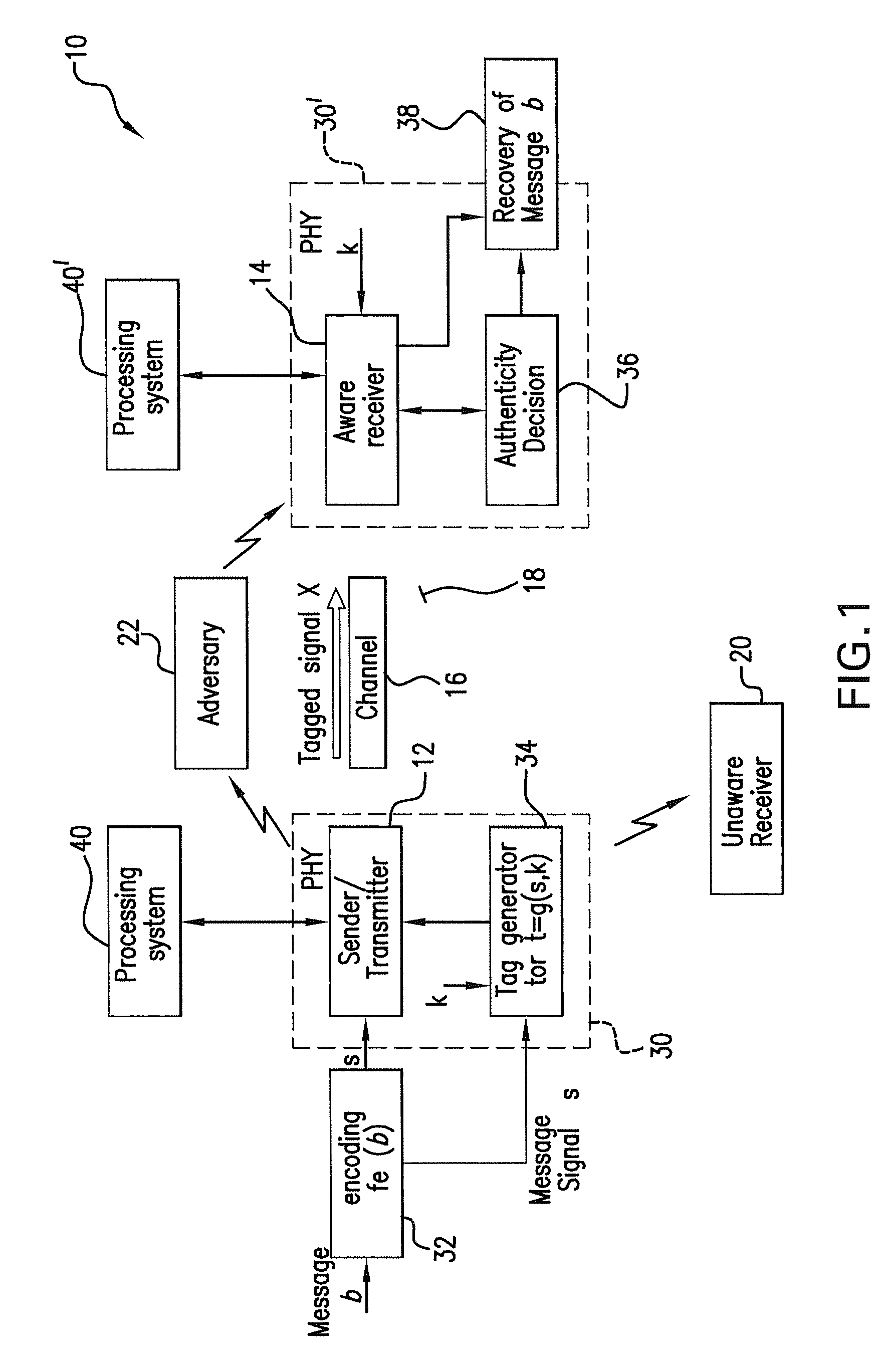
[0047]Referring to FIG. 1, a communication system 10 of the present invention includes a sender / transmitter 12 and an aware receiver 14 which both agree on a keyed authentication scheme to permit the aware receiver 14 to verify the messages received from the sender / transmitter 12. The sender / transmitter 12 and the aware receiver 14 are connected through the transmitting channel 16 for wireless communication therebetween. The sender / transmitter 12 sends the receiver 14 a proof of authentication, e.g., an authentication tag, with each message for the aware receiver's 14 verification. The tagged signal xi=ρssi+ρtti is sent through the transmitting channel 16 from the sender / transmitter 12, wherein the tag ti reflects knowledge of the secret key shared between the sender / transmitter 12 and the aware receiver 14.

[0048]The wireless medium 18 between the sender / transmitter 12 and aware receiver 14 is also shared with the unaware receiver 20 and aware receiver active adversary 22. When the ...


PUM


Abstract

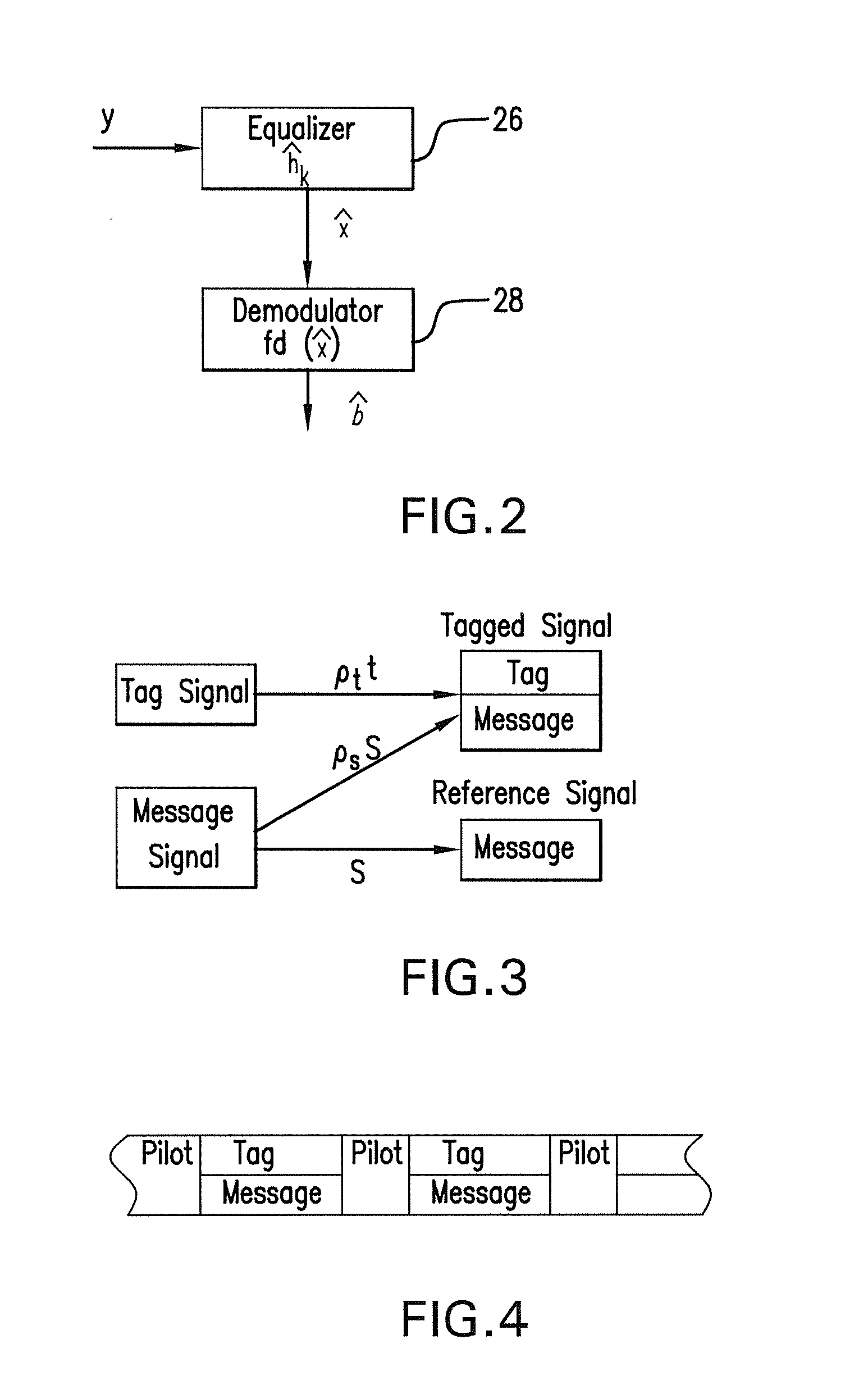
The subject authentication scheme encompasses a large family of authentication systems which may be built over existing transmission systems. By superimposing a carefully designed secret modulation on the waveforms, authentication is added to the signal without requiring additional bandwidth. The authentication information (tag signal) is sent concurrently with data (message signal). The authentication is designed to be stealthy to the uninformed user, robust to interference, and secure for identity verification. The tradeoffs between these three goals are identified and analyzed. The use of the authentication for channel estimation is also considered, and improved bit errors are demonstrated for time-varying channels. With a long enough authentication code word an authentication system is achieved with very slight data degradation. Additionally, by treating the authentication tag as a sequence of pilot symbols, the data recovery may be improved by the aware receiver.

Description

REFERENCE TO RELATED APPLICATIONS[0001]This utility patent application is a Continuation application based on Ser. No. 12 / 676,689, filed on 5 Mar. 2010 which is based on Provisional Patent Application Ser. No. 60 / 970,576 filed 7 Sep. 2007.[0002]The work was funded by the U.S. Government Army Research Lab Contract Number DAAD190120011. The United States Government has certain rights to the Invention.FIELD OF THE INVENTION[0003]The present Invention relates to wireless communication, and in particular, to authenticated communication between a sender and receiver of a signal.[0004]More in particular, the present invention is directed to a wireless communication system in which an authentication scheme is provided at the physical layer of the network system and in which an authenticated message signal is constructed with specific constraints and requirements applied to provide enhanced stealth, robustness and security of the communication.[0005]In overall concept, the present invention ...

Claims


Application Information

Patent Timeline
IPC IPC(8): H04W12/02
CPCH04W12/02H04W12/10H04W12/06H04K3/255H04H20/57H04K3/25H04L9/0875H04L9/3228H04L63/123H04L2209/08H04L2209/80H04W12/106
Inventor BARAS, JOHN S.YU, PAUL L.SADLER, BRIAN M.
Owner US SEC THE ARMY THE
Why Eureka
Eureka Blog
Learn More