
Dual radiation patterns antenna

a radiation pattern and antenna technology, applied in the field of antennas, can solve the problems of inability to achieve high directivity, complexity, cost and antenna size increase, and the inability of wireless transmission systems to transmit and receive data without antennas, so as to improve efficiency and directive of wireless transmission systems, the range of signal receiving and transmitting angles is broadened, and the effect of dual radiation patterns

Inactive Publication Date: 2013-06-27
SJ ANTENNA DESIGN
View PDF10 Cites 30 Cited by
  • Summary
  • Abstract
  • Description
  • Claims
  • Application Information

AI Technical Summary

Benefits of technology

The present invention is about a special type of antenna that can receive and transmit signals from both sides, which makes the range of signal coverage wider. It also improves efficiency and directionality of wireless transmission and makes the antenna smaller.

Problems solved by technology

The wireless transmission system can not transmit and receive data without the antenna.
It is not only complexity, cost and the size of the antenna are increased, but also a high directivity can not be achieved (for example, due to an inadequate system grounding area of the patch antenna).

Method used


Image

  • Dual radiation patterns antenna
  • Dual radiation patterns antenna
  • Dual radiation patterns antenna

Examples


Embodiment Construction

[0014]The present invention will now be described more specifically with reference to the following embodiments. It is to be noted that the following descriptions of preferred embodiments of this invention are presented herein for purpose of illustration and description only, it is not intended to be exhaustive or to be limited to the precise form disclosed.

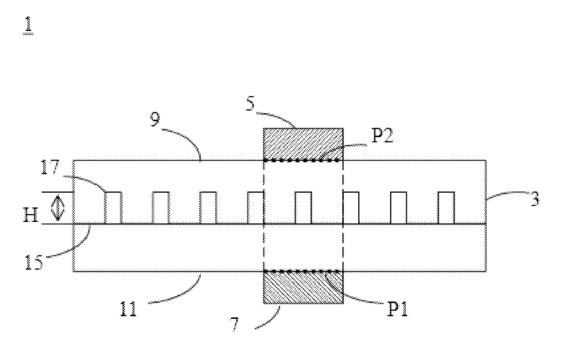
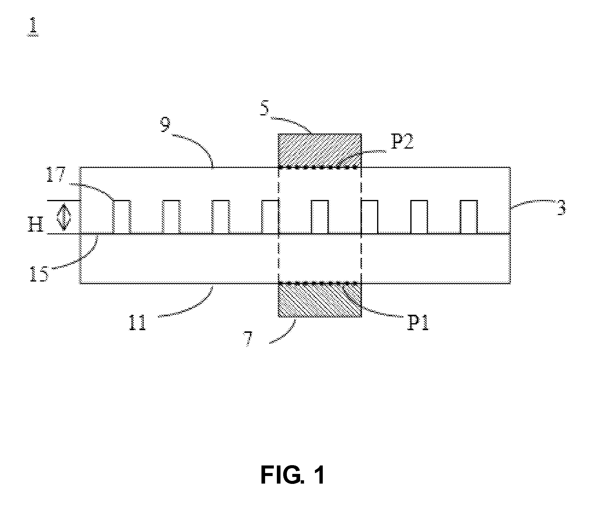
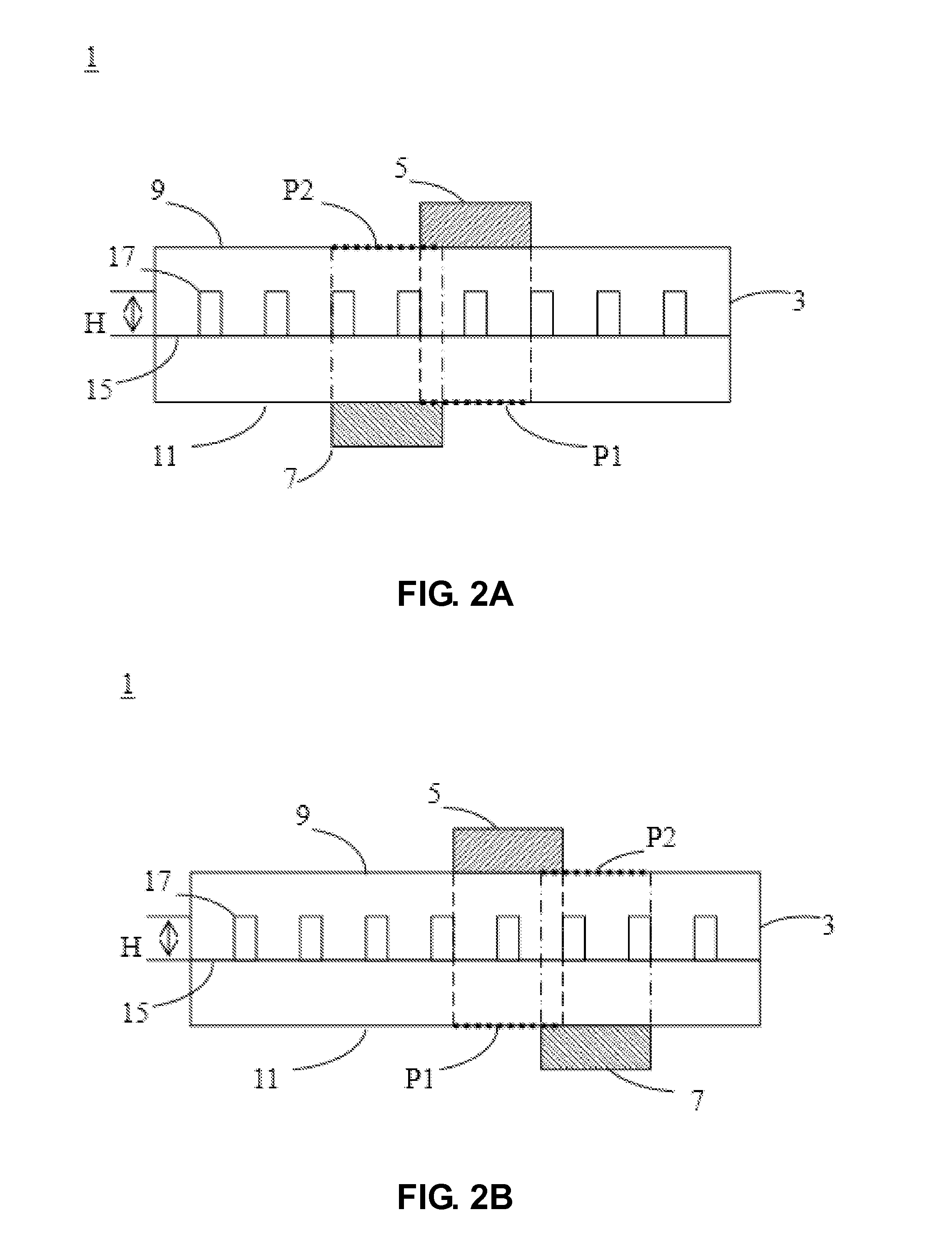
[0015]Please refer to FIG. 1, which schematically shows a cross-section view of the dual radiation patterns antenna according to a first preferred embodiment of the present invention. As shown in FIG. 1, the dual radiation patterns antenna 1 includes a substrate 3, a first antenna unit 5 and a second antenna unit 7. The substrate 3 has a first surface 9 and a second surface 11 opposite to the first surface 9. The substrate 3 is a printed circuit board or a stacked circuit board. The first antenna 5 and the second antenna 7 are formed on the first surface 9 and the second surface 11 of the substrate 3, respectively. A first vertic...


PUM


Abstract

A dual radiation patterns antenna is provided in the present invention. The dual radiation patterns antenna includes a substrate, a first antenna unit and a second antenna unit. The substrate has a first surface and a second surface opposite to the first surface. The first antenna is formed on the first surface of the substrate and used to radiate a first radiation pattern. The second antenna is formed on the second surface of the substrate and used to radiate a second radiation pattern. A first vertical projecting plane of the first antenna unit on the second surface is overlapped with the second antenna unit completely or partially. A second vertical projecting plane of the second antenna unit on the first surface is overlapped with the first antenna unit completely or partially. The first radiation pattern and the second radiation pattern are perpendicular each other.

Description

CROSS-REFERENCE TO RELATED APPLICATION(S)[0001]This application claims the priority benefit of Taiwan patent application No. 100148773, filed on Dec. 26, 2011. The entirety of the above-mentioned patent application is hereby incorporated by reference herein and made a part of this specification.FIELD OF THE INVENTION[0002]The present invention relates to an antenna, and more particular to a dual radiation patterns antenna.BACKGROUND OF THE INVENTION[0003]Due to the rapid development on wireless transmission systems, many new products must have the performance of wireless transmission so as to meet the consumer's requirement. Antenna is an important element for transmitting and receiving electromagnetic wave energy in the wireless transmission system. The wireless transmission system can not transmit and receive data without the antenna. Thus, the antenna is an indispensable element related to a whole performance of the wireless communication system.[0004]Generally, the antennas are ...

Claims


Application Information

Patent Timeline
IPC IPC(8): H01Q9/04H01Q19/30H01Q13/10
CPCH01Q19/30H01Q21/28H01Q13/085H01Q9/0407
Inventor YU, YA CHUNG
Owner SJ ANTENNA DESIGN
Learn More