
Bus bar releasable bushing apparatus

a bushing apparatus and bus bar technology, applied in the direction of insulated conductors, coupling device connections, cables, etc., can solve the problems of reduced electrical connectivity, weak physical connection, and reduced planarity

Active Publication Date: 2013-06-27
ELDRE
View PDF8 Cites 11 Cited by
  • Summary
  • Abstract
  • Description
  • Claims
  • Application Information

AI Technical Summary

Benefits of technology

The present invention relates to a bus bar connection apparatus that does not require soldering, provides reliable electrical connectivity even with disparate conductive materials, and is easily released and replaced in the field. The technical effects of the invention include improved planarity, reduced electrical connectivity and weak physical connection due to the common problem of soldered bushing, as well as increased labor time and material expense due to the need for soldering and associated flattening of the solder to provide a planar surface. The invention provides a solution for these issues by providing a bus bar connection apparatus that is not only removable but also easily replaced in the field.

Problems solved by technology

Generally, the bushings are soldered or welded to the bus bar and therefore suffer from common problems including compromised planarity, particularly in multilayer bus bars, reduced electrical connectivity and weak physical connection due to the introduction of the solder, corrosion, and thermal distortion.
Such prior art bus bars also require substantial labor time and material expense to manufacture due to the soldering of each bushing, and associated flattening of the solder to provide a planar surface, and due to a preference for using relatively expensive copper bushings with copper bus bars due to the difficulty adhering different conductive materials, such as aluminum.
Significantly, soldered bushing are not removable in the field and a failure may require replacement of the whole bus bar assembly.
While such connection apparatus do not require soldering and still provide reliable electrical connectivity, they are only removable using a tool to engage a detent in the retainer thereby requiring additional time for replacement in the field as well as increased likelihood of deformation of the retainer or other portion of the connection apparatus.

Method used


Image

  • Bus bar releasable bushing apparatus
  • Bus bar releasable bushing apparatus
  • Bus bar releasable bushing apparatus

Examples


Embodiment Construction

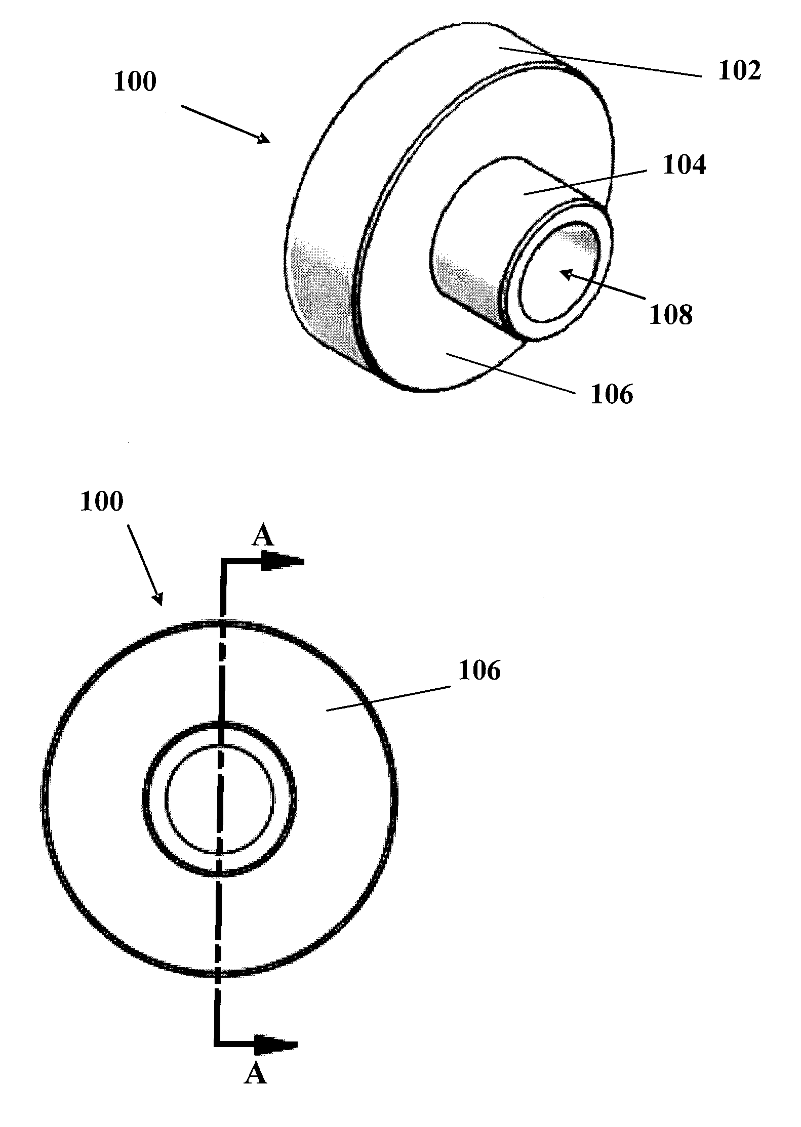
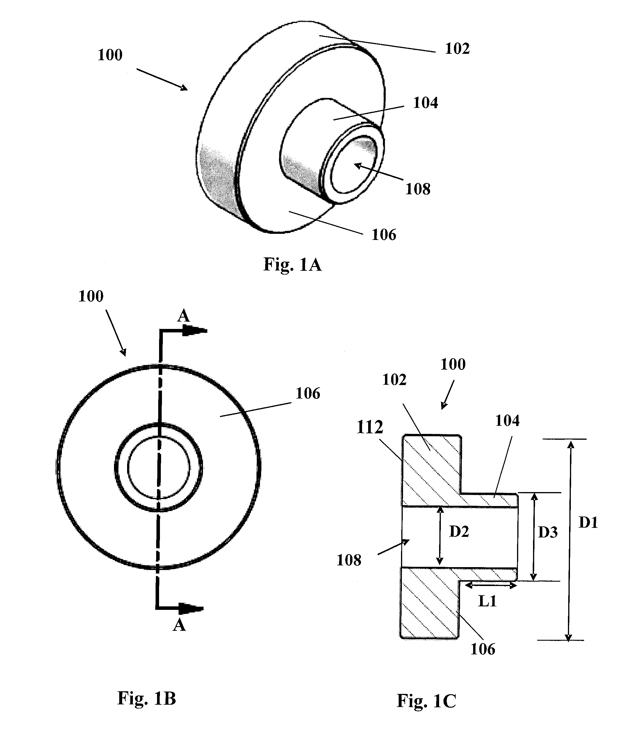
[0031]Referring to FIG. 1A-1C, a male bushing portion 100 according to some embodiments of the present invention is shown. The male bushing portion 100 can be any suitable electrically conductive material such as copper or aluminum, for example. The male bushing portion 100 includes a body 102 which can be cylindrical, hexagonal, or any other shape including at least a first planar surface 106. Preferably, the male bushing portion body 102 includes opposing first 106 and second 112 substantially planar surfaces and is a hollow cylinder or toroid in shape including an outer diameter D1 and an axial bore 108 defining an inner diameter D2.

[0032]Extending from the first planar surface 106 of the body 102 is a shoulder 104 having a length L1, an outer diameter D3 and an axial bore 108 defining an inner diameter D2. In the exemplary embodiment shown, the diameter D2 of the axial bore 108 is substantially the same through the body 102 and shoulder 104. However, in some embodiments, the dia...


PUM


Abstract

A bus bar component connection apparatus including an electrically conductive bus bar having a thickness and at least one bore, the bore having a diameter, a male bushing portion including a body having two opposing planar surfaces, at least one shoulder extending from the body at a first end and including a threaded portion disposed toward a second end and spaced from the first end by an undercut portion, and an axial bore through the body and the shoulder, a female bushing portion having two opposing planar surfaces, a first end, a second end, and an inner surface including a threaded portion disposed toward the second end and spaced from the first end by a first smooth portion, and wherein the female bushing portion is configured to threadably receive the shoulder through the hole of the bus bar.

Description

CROSS-REFERENCE TO RELATED APPLICATIONS[0001]This application claims priority to U.S. Provisional Patent Application Ser. No. 61 / 567,763 filed Dec. 7, 2011, the specification of which is hereby incorporated by reference in its entirety.TECHNICAL FIELD[0002]The present invention relates to power distribution systems and more particularly, to bus bar component connection apparatus.BACKGROUND INFORMATION[0003]Power distribution systems, or bus bars, are conductive plates including a plurality of holes for receiving electrical components such as insulated gate bi-polar transistor (IGBT) modules or circuit breakers, for example. The conductive plates may be made of any, and / or plated by, conductive material such as copper, aluminum, brass, or nickel, for example. The electrical components have various connection apparatus, including bushings, disposed proximate the bus bar holes. Generally, the bushings are soldered or welded to the bus bar and therefore suffer from common problems inclu...

Claims


Application Information

Patent Timeline
IPC IPC(8): H01R13/00
CPCH01R4/60H01R31/06H01R4/30H02G5/007H01R13/00
Inventor ERDLE, HARVEY B.PETOTE, THOMAS A.ARIENO, JOSEPH THOMASERDLE, JESSE A.
Owner ELDRE
Learn More