
Leak detection device, and coating intended for a fluid transport or storage member and comprising said detection device

a detection device and detection device technology, applied in the direction of fluid tightness measurement, structural/machine measurement, instruments, etc., can solve the problems of reducing the detection accuracy of leak detection devices, and reducing so as to reduce the risk of being burnt, reduce the risk of leakage detection, and facilitate installation

Active Publication Date: 2013-06-20
COMMISSARIAT A LENERGIE ATOMIQUE ET AUX ENERGIES ALTERNATIVES
View PDF19 Cites 18 Cited by
  • Summary
  • Abstract
  • Description
  • Claims
  • Application Information

AI Technical Summary

Benefits of technology

The invention provides an improved device for detecting leaks of fluids in ducts or containers. The device incorporates a covering made of a conductive material that prevents short circuits and also allows for the intentional creation of short circuits for checking the operation of the leak detector device. The flexible insulating material, such as mineral fiber wool, can adapt to deformations of the equipment and provides thermal insulation to limit heat loss and protect operators. The invention also provides a simple method for covering ducts of complex shape.

Problems solved by technology

A drawback of that device stems from the difficulty of making a shell, or a half-shell, that is a good fit to the outside surface of the duct for which it is intended, in particular when said outside surface is complex in shape.
A drawback of that device results from the difficulty in shaping the fabric or grid so that it fits closely to the insulating sheet without some portion of the fabric or grid penetrating into the insulating sheet and thereby involuntarily establishing contact between the fabric or grid and the wall of the duct, which is generally made of metal.
Furthermore, fabrics, grids, tapes, or wires made of metal run the risk of oxidizing.
Under such circumstances, the formation of a film of oxide on the surface of such a metal conductive element can impede or slow down the detection of a short circuit between said element and the wall of the duct, and can consequently impede or slow down the detection of a leak.
Furthermore, such conductive metal elements may deform by thermal expansion during variations in the temperature of the duct, and that also can lead to a malfunction of the leak detector system.

Method used


Image

  • Leak detection device, and coating intended for a fluid transport or storage member and comprising said detection device
  • Leak detection device, and coating intended for a fluid transport or storage member and comprising said detection device
  • Leak detection device, and coating intended for a fluid transport or storage member and comprising said detection device

Examples


Embodiment Construction

[0048]Unless stated explicitly or implicitly to the contrary, elements or members that are structurally or functionally identical or similar are given identical references in the various figures.

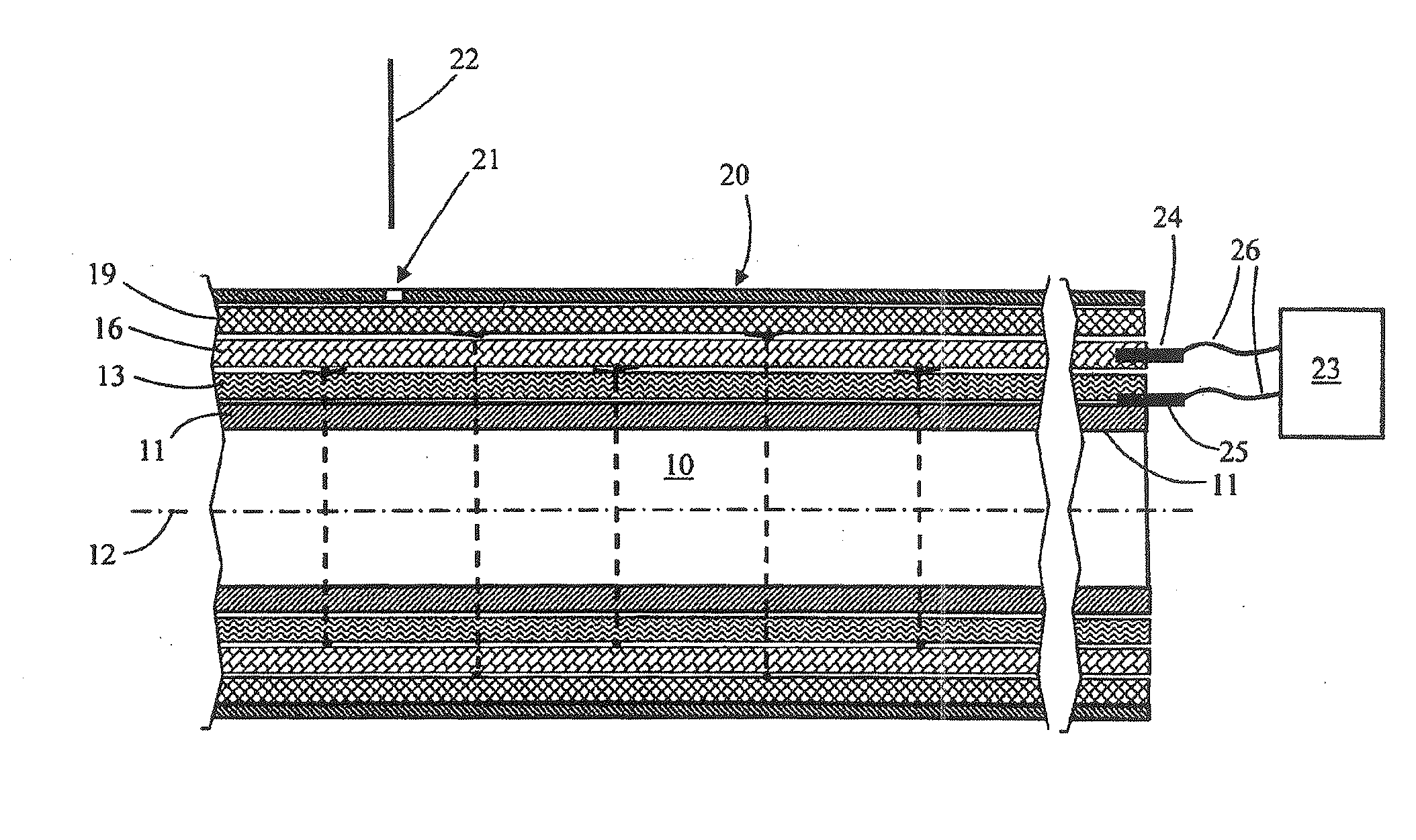
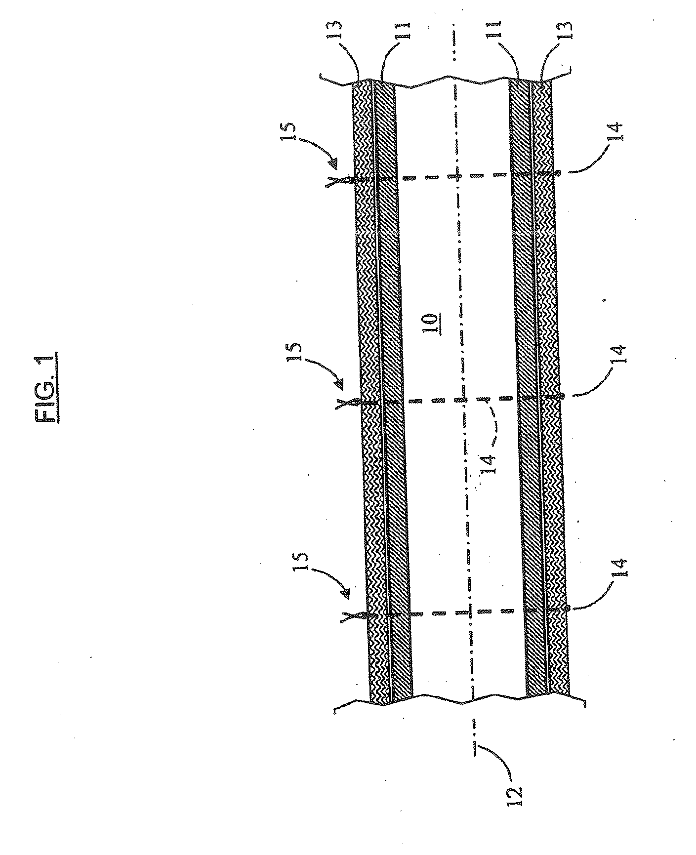
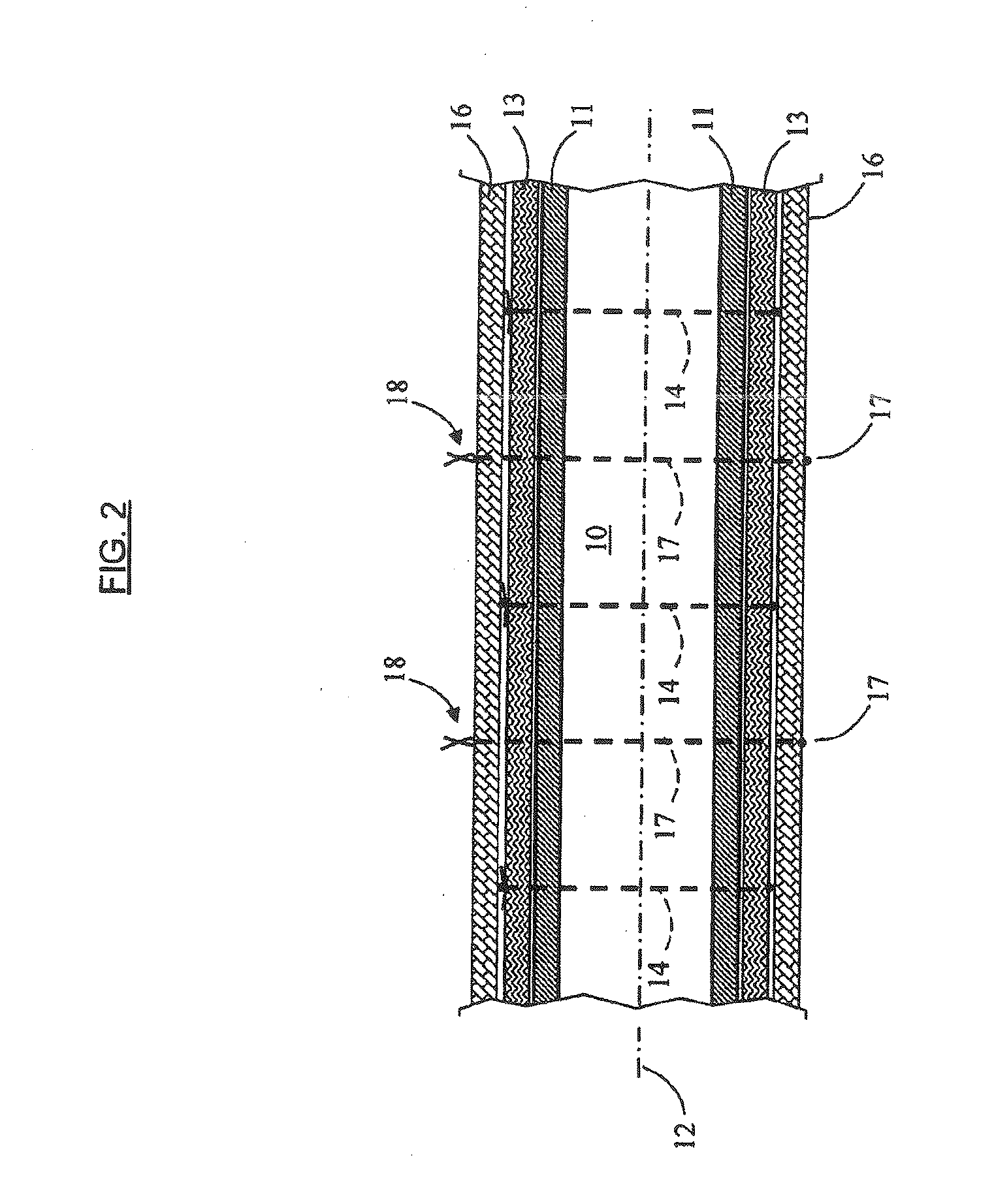
[0049]With reference to FIGS. 1 to 5, a duct 10 for transporting liquid sodium under pressure has a cylindrical wall 11 extending along a longitudinal axis 12. The wall 11 may be made of stainless steel.

[0050]With reference to FIG. 1 in particular, a layer of insulating fibrous material 13 has been wound, or laid in some other way, around the wall 11 and is held in contact with the outside face of that wall by cords 14 surrounding the layer of material 13 and knotted (references 15) in order to form closed loops surrounding the layer 13.

[0051]By way of example, the material 13 may be a mineral fiber wall sold under the name “Superwool 607 Blanket” by the supplier Thermal Ceramics (USA).

[0052]This layer of mineral wool may present thickness of about 2 millimeters, and up to about 5, 10, or mi...


PUM

PropertyMeasurementUnit
Thicknessaaaaaaaaaa
Thicknessaaaaaaaaaa
Thicknessaaaaaaaaaa

Abstract

The invention relates in particular to a method of covering a duct for transporting or storing a fluid in a device for detecting a leak of the fluid, the device comprising a layer of insulating fibrous material arranged to surround the duct and a layer of conductive material that extends against the layer of insulating material, the conductive material being essentially constituted by fibers of carbon or graphite, wherein the layer of insulating material is secured to the wall of the duct by strapping ties around said layer.

Description

TECHNICAL FIELD[0001]The present invention relates to a device for detecting leaks and to a covering for a member for transporting or storing fluid, the covering including the detector device.[0002]The invention also relates to a member for transporting or storing fluid and fitted with such a covering, to a method of covering a member for transporting or storing fluid, and to a method of checking that such a leak detector device is operating properly.[0003]The invention applies in particular to covering ducts for transporting liquid sodium and to containers for storing sodium and forming part of a cooling circuit of a nuclear reactor.[0004]Below in the present application, and unless indicated explicitly or implicitly to the contrary, the term “duct” is used to designate equally well a duct for transporting fluid or a container for storing fluid and also an accessory, such as a valve, fitted to such a duct or container.STATE OF THE ART[0005]In particular for sodium transport ducts, ...

Claims


Application Information

Patent Timeline
IPC IPC(8): G01M3/40
CPCG01M3/165Y10T29/49947G01M3/40G01M3/18Y02E30/30G01M3/16G21C17/00
Inventor ALBALADEJO, SERGEZANOLIN, REMI
Owner COMMISSARIAT A LENERGIE ATOMIQUE ET AUX ENERGIES ALTERNATIVES
Learn More